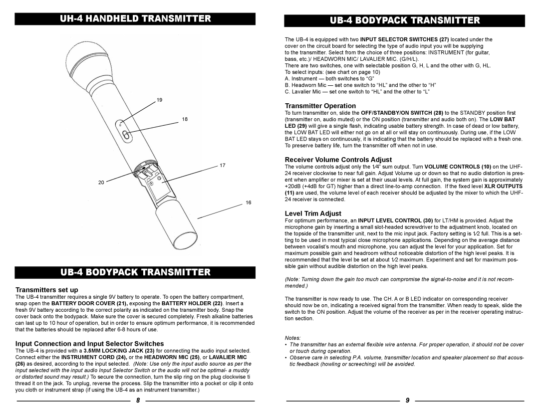
UH-4 HANDHELD TRANSMITTER
17
16
UB-4 BODYPACK TRANSMITTER
Transmitters set up
The
Input Connection and Input Selector Switches
The
(26)as desired, according to the input selected. (Note: Use only the input audio source as per the input selected with the input audio Input Selector Switch or the audio will not be optimal- a muddy or distorted sound may result.) To secure the connection, turn the slip ring on the plug clockwise ti thread it on the jack. To unplug, reverse the process. Slip the transmitter into a pocket or clip it onto you cloth or instrument strap (if using the
UB-4 BODYPACK TRANSMITTER
The
to the transmitter. Select from the choice of three positions: INSTRUMENT (for guitar, bass, etc.)/ HEADWORN MIC/ LAVALIER MIC. (G/H/L).
There are two switches, one with selectable position G, H, L and the other with G, HL. To select inputs: (see chart on page 10)
A. Instrument — both switches to “G”
B. Headworn Mic — set one switch to “HL” and the other to “H” C. Lavalier Mic — set one switch to “HL” and the other to “L”
Transmitter Operation
To turn transmitter on, slide the OFF/STANDBY/ON SWITCH (28) to the STANDBY position fi rst (transmitter on, audio muted) or the ON position (transmitter and audio both on). The LOW BAT LED (29) will give a single fl ash, indicating usable battery strength. In case of dead or low battery, the LOW BAT LED will either not go on at all or will stay on continuously. During use, if the LOW BAT LED stays on continuously, it is indicating that the battery should be replaced with a fresh one. To preserve battery life, turn the transmitter off when not in use.
Receiver Volume Controls Adjust
The volume controls adjust only the 1⁄4” sum output. Turn VOLUME CONTROLS (10) on the UHF- 24 receiver clockwise to near full gain. Adjust Volume up or down so that no audio distortion is pres- ent when amplifi er or mixer is set at their usual levels. At full gain, the system gain is approximately +20dB (+4dB for GT) higher than a direct
(11)are used, the volume level of each receiver should be adjusted by the mixer to which the UHF- 24 receiver is connected.
Level Trim Adjust
For optimum performance, an INPUT LEVEL CONTROL (30) for LT/HM is provided. Adjust the microphone gain by inserting a small
(Note: Turning down the gain too much can compromise the
The transmitter is now ready to use. The CH. A or B LED indicator on corresponding receiver should now be on, indicating a received signal from the transmitter. When ready to speak, slide the switch to the ON position. Adjust the volume of the receiver as per in the receiver operating instruc- tion section.
Notes:
•The transmitter has an external fl exible wire antenna. For proper operation, it should not be cover or touch during operation.
•Observe care in selecting P.A. volume, transmitter location and speaker placement so that acous- tic feedback (howling or screeching) will be avoided.
8 | 9 |