
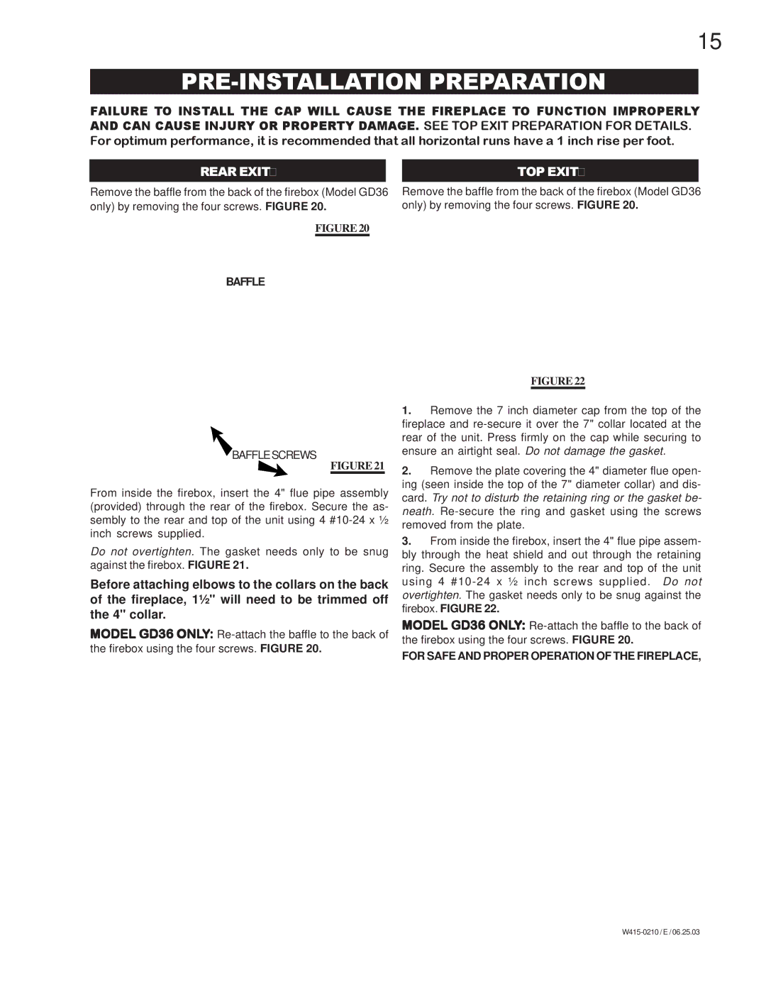
BGD36PTR, BGD36NTR, GD36PTR, GD36NTR specifications
Napoleon Fireplaces is a brand renowned for its commitment to quality, innovation, and style in home heating solutions. Among their exceptional offerings are the GD36NTR, GD36PTR, BGD36NTR, and BGD36PTR models, which epitomize modern gas fireplace design with an array of features, technologies, and characteristics.The GD36NTR (Natural Gas) and GD36PTR (Propane) models are designed to provide warmth and ambiance with elegance. These fireplaces boast a compact yet stylish design that fits seamlessly into any living space. The impressive heat output ranges up to 30,000 BTUs, ensuring a cozy environment even in the coldest months. The included large glass viewing area enhances the aesthetics of the fireplace, allowing for an unobstructed view of the mesmerizing flames.
Equipped with Napoleon’s advanced heat radiating system, the GD36 series enhances warmth distribution, making it efficient and effective. The innovative electronic ignition ensures that lighting the fireplace is easy and reliable, offering both convenience and safety.
In contrast, the BGD36 series, consisting of BGD36NTR and BGD36PTR, brings a different approach with its built-in design suited for new constructions and renovations. These models emphasize versatility and adaptability, fitting into a variety of settings. The BGD36 models similarly deliver aesthetic appeal with their expansive glass front, and they feature a powerful heat output of up to 30,000 BTUs.
Both the GD36 and BGD36 series integrate Napoleon’s patented PHAZER® Log Set that mimics the look of real wood logs, ensuring a lifelike flame experience. The adjustable flame height feature allows users to customize the ambiance according to their moods, ranging from a gentle glow to full, roaring flames.
Another remarkable feature is the multi-function remote control that provides fingertip access to all fireplace functions, enhancing user experience. Complementing these features is the inclusion of a safety screen, which ensures that families can enjoy their fires with peace of mind.
Both series highlight energy efficiency, complying with strict environmental regulations while providing the coziness expected from a traditional fireplace. With their stylish designs, innovative technologies, and commitment to safety and efficiency, the Napoleon Fireplaces GD36NTR, GD36PTR, BGD36NTR, and BGD36PTR make the perfect addition to any home, blending warmth and modern sophistication.