21
OPTIONAL SWITCH / WIRING DIAGRAM
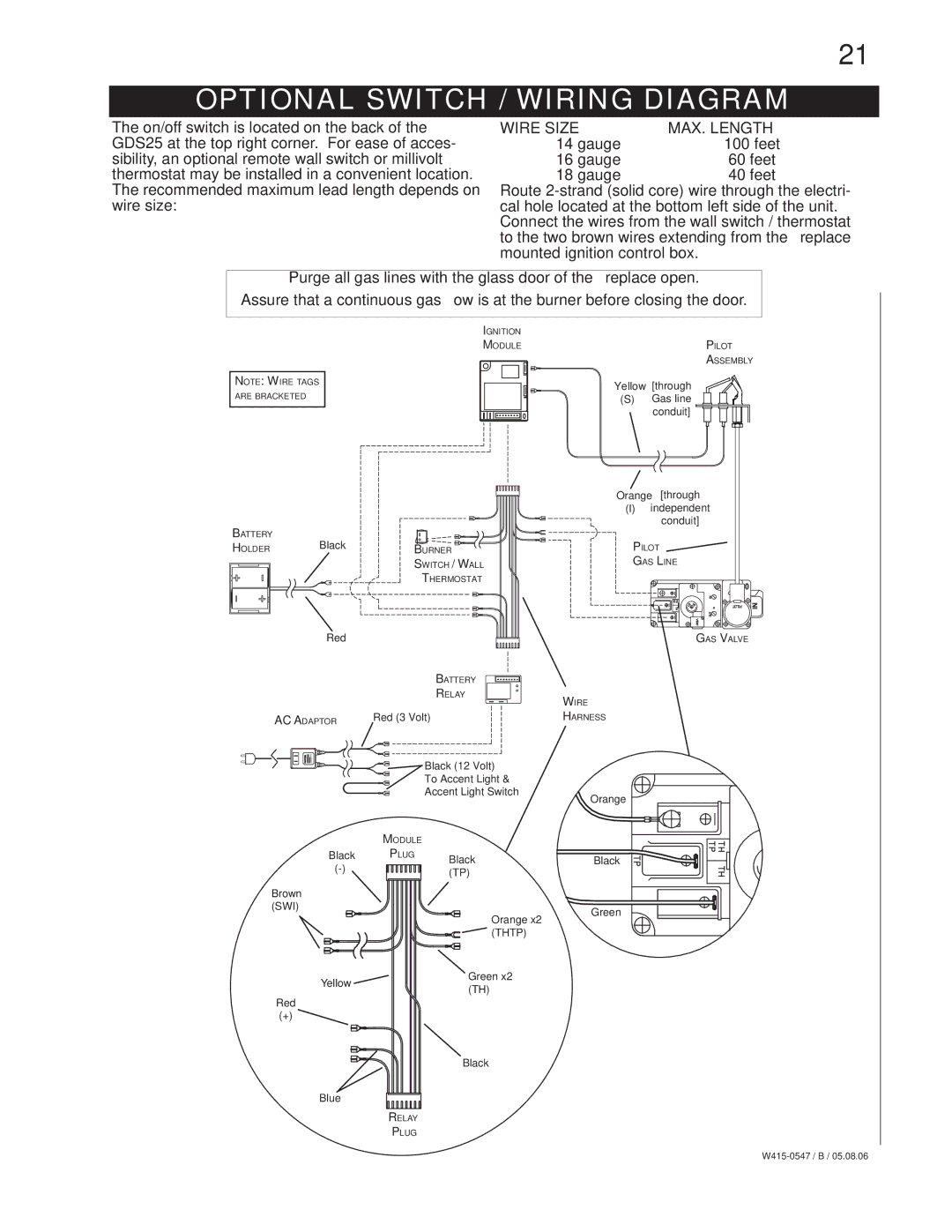
The on/off switch is located on the back of the GDS25 at the top right corner. For ease of acces- sibility, an optional remote wall switch or millivolt thermostat may be installed in a convenient location. The recommended maximum lead length depends on wire size:
WIRE SIZE | MAX. LENGTH |
14 gauge | 100 feet |
16 gauge | 60 feet |
18 gauge | 40 feet |
Route
Purge all gas lines with the glass door of the fireplace open.
Assure that a continuous gas flow is at the burner before closing the door.
IGNITION
MODULE
NOTE: WIRE TAGS
ARE BRACKETED
BATTERY | Black |
|
HOLDER | BURNER | |
|
| SWITCH / WALL |
|
| THERMOSTAT |
Red
BATTERY
RELAY
AC ADAPTOR | Red (3 Volt) |
PILOT
ASSEMBLY
Yellow [through
(S)Gas line conduit]
Orange [through
(I)independent
conduit]
PILOT
GAS LINE
GAS VALVE
WIRE
HARNESS
Black (12 Volt)
To Accent Light &
Accent Light Switch
Orange
MODULE
Black PLUG Black
Black |
Brown |
|
|
|
(SWI) |
| Orange x2 | Green |
|
| ||
|
|
| |
|
| (THTP) |
|
| Yellow | Green x2 |
|
| (TH) |
| |
Red |
|
| |
|
|
| |
(+) |
|
|
|
Black
Blue
RELAY
PLUG