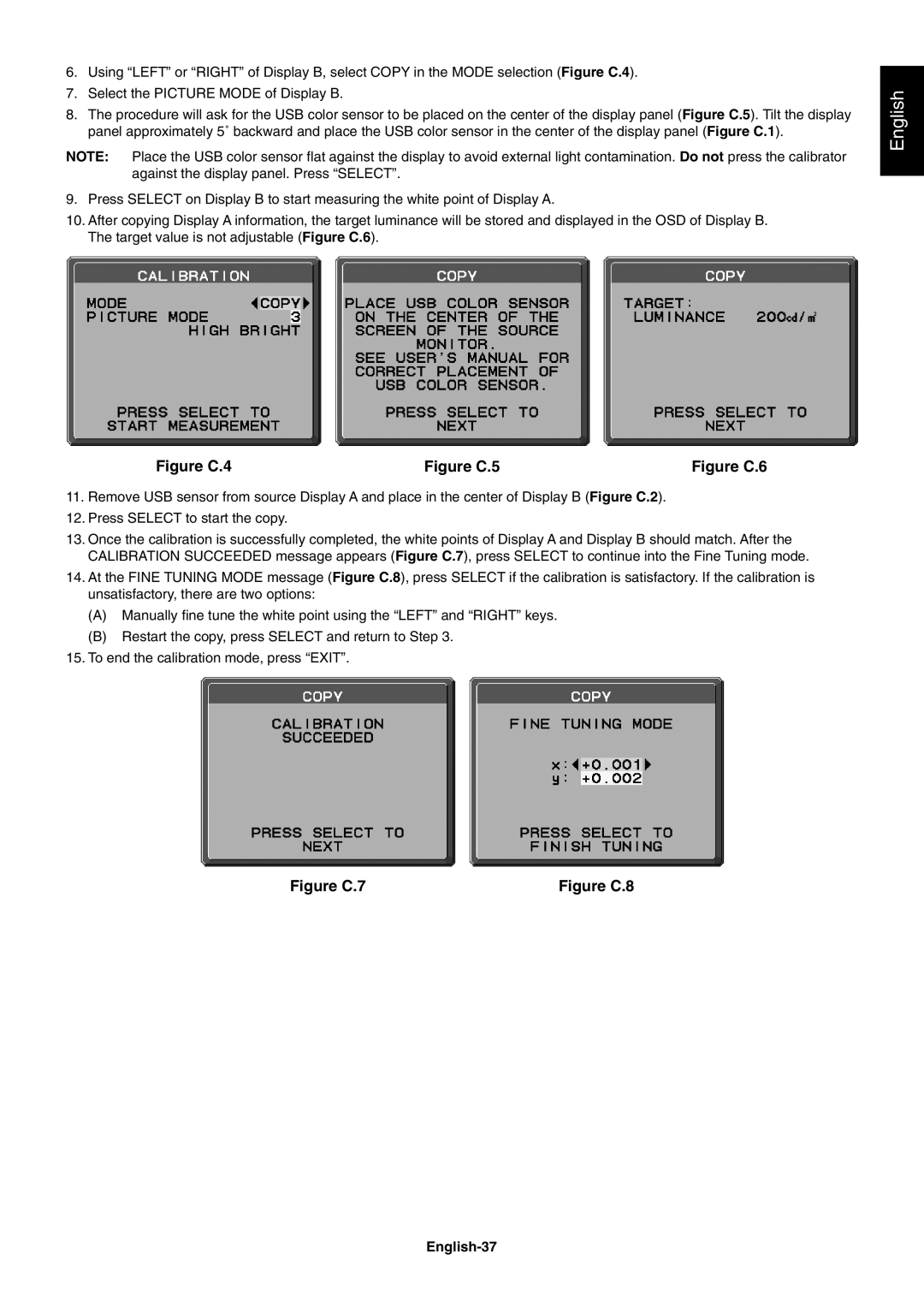
6.Using “LEFT” or “RIGHT” of Display B, select COPY in the MODE selection (Figure C.4).
7.Select the PICTURE MODE of Display B.
8.The procedure will ask for the USB color sensor to be placed on the center of the display panel (Figure C.5). Tilt the display panel approximately 5˚ backward and place the USB color sensor in the center of the display panel (Figure C.1).
NOTE: Place the USB color sensor fl at against the display to avoid external light contamination. Do not press the calibrator against the display panel. Press “SELECT”.
9.Press SELECT on Display B to start measuring the white point of Display A.
10.After copying Display A information, the target luminance will be stored and displayed in the OSD of Display B. The target value is not adjustable (Figure C.6).
English
Figure C.4 | Figure C.5 | Figure C.6 |
11.Remove USB sensor from source Display A and place in the center of Display B (Figure C.2).
12.Press SELECT to start the copy.
13.Once the calibration is successfully completed, the white points of Display A and Display B should match. After the CALIBRATION SUCCEEDED message appears (Figure C.7), press SELECT to continue into the Fine Tuning mode.
14.At the FINE TUNING MODE message (Figure C.8), press SELECT if the calibration is satisfactory. If the calibration is unsatisfactory, there are two options:
(A)Manually fi ne tune the white point using the “LEFT” and “RIGHT” keys.
(B)Restart the copy, press SELECT and return to Step 3.
15.To end the calibration mode, press “EXIT”.
Figure C.7 | Figure C.8 |
