GS748T Gigabit Smart Switch
Step 4: Connect Devices to the Switch
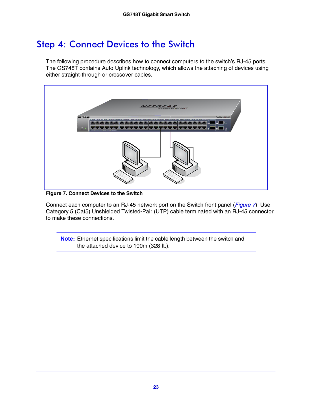
The following procedure describes how to connect computers to the switch’s
Reset
Power
1 | 2 | 3 | 4 | 5 | 6 | 7 | 8 | 9 | 10 | 11 | 12 | 13 | 14 | 15 | 16 | 17 | 18 | 19 | 20 | 21 | 22 | 23 | 24 | 25 | 26 | 27 | 28 | 29 | 30 | 31 | 32 | 33 | 34 | 35 | 36 | 37 | 38 | 39 | 40 | 41 | 42 | 43 | 44 | 45T | 46T | 47T | 48T | Combo |
|
|
|
|
|
|
|
|
|
|
|
|
|
|
|
|
|
|
|
|
|
|
|
|
|
|
|
|
|
|
|
|
|
|
|
|
|
| Ports | ||||||||||
|
|
|
|
|
|
|
|
|
|
|
|
|
|
|
|
|
|
|
|
|
|
|
|
|
|
|
|
|
|
|
|
|
|
|
|
|
|
|
|
|
|
|
|
|
|
|
| 47F |
|
|
|
|
|
|
|
|
|
|
|
|
|
|
|
|
|
|
|
|
|
|
|
|
|
|
|
|
|
|
|
|
|
|
|
|
|
|
|
|
|
|
|
|
|
|
|
| 48F |
| LED Link/Act Mode Green=Link at 1000M Yellow=Link at 100/10M Blink=ACT |
|
|
|
|
|
|
|
|
|
|
|
|
|
|
|
|
|
|
|
|
|
|
|
|
|
|
|
|
|
|
|
|
|
|
|
|
|
| |||||||||
|
|
|
|
|
|
|
|
|
|
|
|
|
|
|
|
|
|
|
|
| ` |
|
|
|
|
|
|
|
|
|
|
|
|
|
|
|
|
|
|
| ` |
|
|
|
|
|
| |
![]()
![]()
![]()
![]()
![]()
![]()
![]() GS748T
GS748T
| SFP LED |
| GREEN= |
| 100/ |
49 | 1000Mbps |
Blink=ACT | |
50 | Factory |
| Default |
Figure 7. Connect Devices to the Switch
Connect each computer to an
Note: Ethernet specifications limit the cable length between the switch and the attached device to 100m (328 ft.).
23