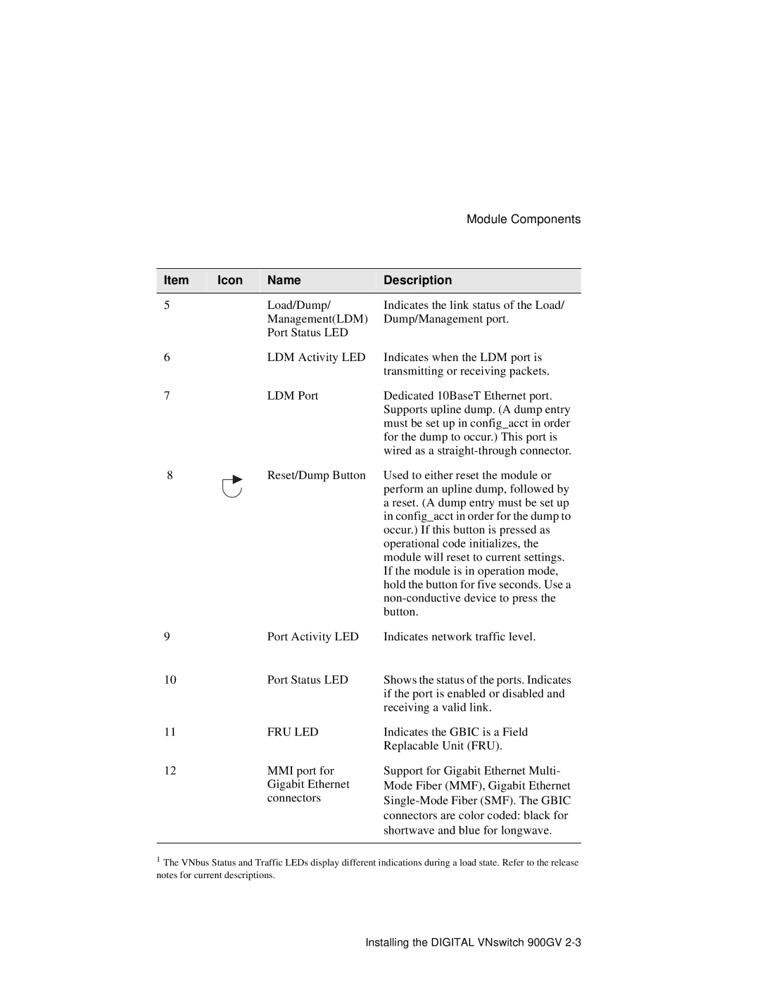
900GV specifications
Network Technologies 900GV is an advanced networking solution designed to meet the demands of today's high-performance environments. As organizations increasingly rely on seamless connectivity and robust data transmission, the 900GV stands out due to its exceptional capabilities. One of its key features is its ability to deliver high-speed data transfer across extensive distances, making it an ideal choice for both enterprise and industrial applications.The 900GV harnesses advanced wireless technology, allowing for reliable communication without the constraints of wired connections. This flexibility enables organizations to deploy their networks in challenging geographical locations or areas where prolonged cabling might be impractical. The device is particularly noted for utilizing a proprietary modulation scheme, which enhances data throughput while minimizing latency. This is especially vital for businesses that require real-time data exchange, such as financial institutions or large-scale manufacturing operations.
Another distinctive aspect of the 900GV is its built-in redundancy mechanisms. With dual power inputs and failover capabilities, the device ensures that network connectivity remains uninterrupted even in adverse conditions. This reliability is vital for mission-critical environments where downtime can result in significant losses or operational disruptions. The 900GV also features advanced security protocols, including encryption options that safeguard data against unauthorized access, thereby instilling confidence in users regarding the safety of their networks.
Moreover, the Network Technologies 900GV is compatible with various networking standards, making it an incredibly versatile solution. It supports various protocols, including Ethernet and IP, which further enhances its integration capabilities within existing network architectures. The device is designed with user-friendly diagnostics tools that simplify network management and monitoring, allowing IT teams to address potential issues proactively.
In conclusion, Network Technologies 900GV is a premier networking solution that combines high-speed data transfer, reliable connectivity, and robust security features. Its adaptability to various environments and protocols makes it essential for organizations looking to enhance their network infrastructure. With its state-of-the-art technology and comprehensive characteristics, the 900GV is poised to meet the evolving demands of modern networking and communication.

