PS/2 KVM specifications
Network Technologies PS/2 KVM switches are essential devices that enable users to control multiple computers from a single set of keyboard, video, and mouse (KVM) peripherals. These devices are particularly advantageous in server rooms, data centers, and environments where space-saving is crucial, as they streamline the management and minimize the clutter of multiple keyboards and monitors.A key feature of PS/2 KVM switches is their compatibility with the PS/2 interface, which has been a standard for connecting keyboards and mice for many years. This ensures reliable communication and seamless performance when managing various systems. The switch typically supports a wide range of resolutions, allowing users to connect to different video outputs without sacrificing image quality. Most PS/2 KVM setups can handle resolutions up to 1920x1200, making them suitable for high-definition applications.
One of the primary technologies utilized in PS/2 KVM switches is multi-platform support. This allows users to connect and control computers running different operating systems simultaneously, including Windows, Linux, and UNIX. This versatility is essential in environments with varied system requirements and contributes to improved operational efficiency.
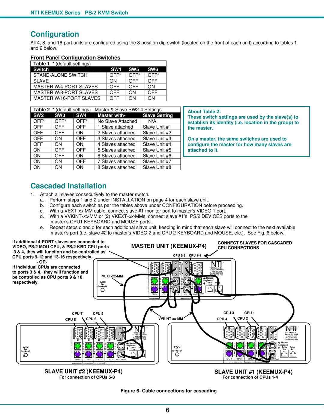
In terms of scalability, many PS/2 KVM switches support daisy chaining and cascading, enabling the connection of multiple switches for managing even larger numbers of servers. This is particularly helpful for administrators who need to manage extensive infrastructures without the hassle of additional hardware.
PS/2 KVM switches also come with features such as hotkey switching, which allows users to switch between computers using keyboard shortcuts. This functionality enhances workflow efficiency, as users can quickly access different systems without the need for manual intervention. Additionally, they often include LED indicators that simplify status monitoring, ensuring users are aware of which systems are currently active.
Security is another critical aspect. Many PS/2 KVM switches offer the option to implement password protection and encryption protocols, safeguarding sensitive data during operations.
In summary, Network Technologies PS/2 KVM switches provide a robust and effective solution for managing multiple computers in various settings. Their combination of compatibility, resolution support, scalability, and security features makes them a valuable asset for IT professionals looking to enhance productivity and streamline operations.

