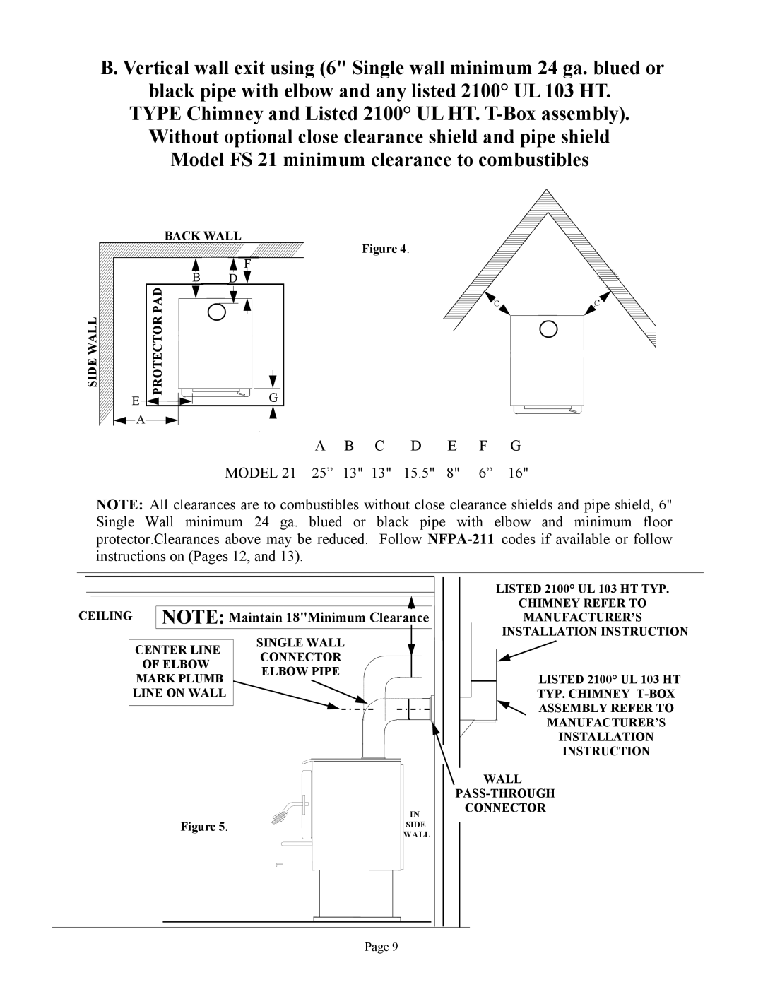
B. Vertical wall exit using (6" Single wall minimum 24 ga. blued or black pipe with elbow and any listed 2100° UL 103 HT.
TYPE Chimney and Listed 2100° UL HT.
SIDE WALL
EE
![]()
![]() A
A
BACK WALL
Figure 4.
B | H D FF |
B | G |
PADPROTECTOR![]()
![]()


![]()
![]() G
G
CC ![]()
![]() C
C
| A | B C | D | E | F | G |
MODEL 21 | 25” | 13" 13" | 15.5" | 8" | 6” | 16" |
|
|
|
|
|
|
|
NOTE: All clearances are to combustibles without close clearance shields and pipe shield, 6" Single Wall minimum 24 ga. blued or black pipe with elbow and minimum floor protector.Clearances above may be reduced. Follow
CEILING
SINGLE WALL
CONNECTOR
ELBOW PIPE
Figure 5.
IN
SIDE WALL
LISTED 2100° UL 103 HT TYP.
CHIMNEY REFER TO
MANUFACTURER’S INSTALLATION INSTRUCTION
LISTED 2100° UL 103 HT
TYP. CHIMNEY
ASSEMBLY REFER TO
MANUFACTURER’S
INSTALLATION
INSTRUCTION
WALL
CONNECTOR
Page 9