16. DATA OUTPUT TO EXTERNAL EQUIPMENT
The data on measured range is output to a remote display or computer across connector X2.
To output the data, it is necessary to apply the supply voltage of 3 to 8 V from the equipment to be connected to the range finder to pin 9 of connector X2. The amplitude of the output signals will depend on the value of the supplied voltage.
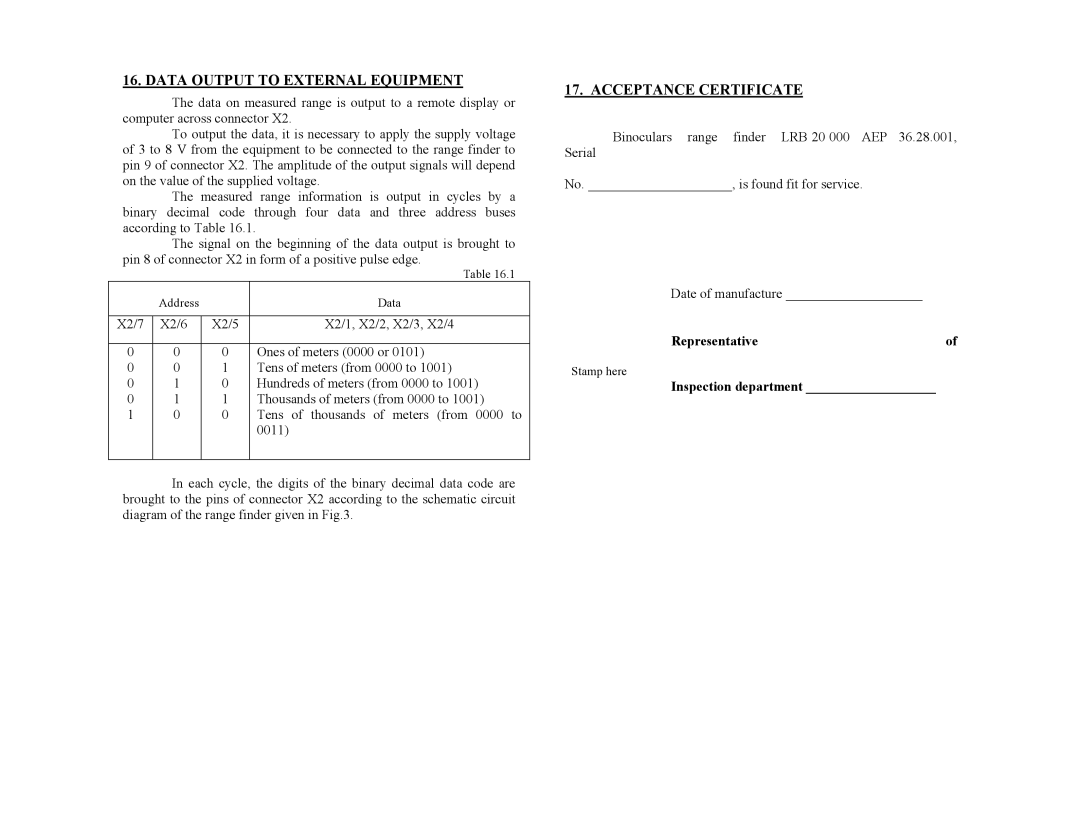
The measured range information is output in cycles by a binary decimal code through four data and three address buses according to Table 16.1.
The signal on the beginning of the data output is brought to pin 8 of connector X2 in form of a positive pulse edge.
|
|
| Table 16.1 |
| Address |
| Data |
|
|
|
|
X2/7 | X2/6 | X2/5 | X2/1, X2/2, X2/3, X2/4 |
|
|
|
|
0 | 0 | 0 | Ones of meters (0000 or 0101) |
0 | 0 | 1 | Tens of meters (from 0000 to 1001) |
0 | 1 | 0 | Hundreds of meters (from 0000 to 1001) |
0 | 1 | 1 | Thousands of meters (from 0000 to 1001) |
1 | 0 | 0 | Tens of thousands of meters (from 0000 to |
|
|
| 0011) |
|
|
|
|
In each cycle, the digits of the binary decimal data code are brought to the pins of connector X2 according to the schematic circuit diagram of the range finder given in Fig.3.
17. ACCEPTANCE CERTIFICATE
Binoculars range finder LRB 20 000 AEP 36.28.001,
Serial
No. _____________________, is found fit for service.
Date of manufacture ____________________ |
|
Representative | of |
Stamp here |
|
Inspection department ___________________ |
|
