LCD display
4 x 20 character line to display 2 events
System disabled |
|
illuminated when | Press to reveal |
detectors or inputs | |
are isolated | more messages on |
| the LCD display |
General fault | Silence alarms |
|
illuminates when | control. Press | Press to test the |
a general system | to silence the | alarm sounders. |
fault has occurred | alarms. | Release to clear. |
|
|
|
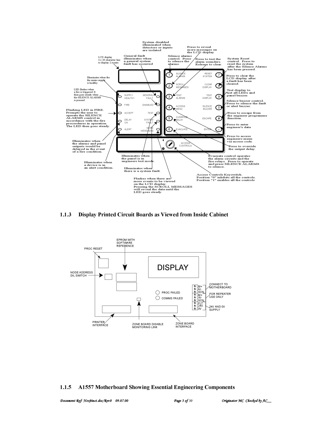
System Reset control. Press to reset the system
after the Silence Alarms has been pressed.
Illuminates when the the mains supply
is healthy.
LED flashes when a fire is triggered. It then goes steady when the SILENCE ALARMS is pressed.
Flashing LED in FIRE. Prompts the user to operate the SILENCE ALARMS control in accordance with the fire proceedures in operation. The LED then goes steady.
SUPPLY | GENERAL | |
HEALTHY | FAULT | |
FIRE | DISABLED | |
ACCEPT | TEST | |
DELAY | SYSTEM | |
ON | FAULT | |
ALERT | MORE | |
MESSAGES | ||
|
1 | SILENCE | RESET | 7 | |
ALARMS | SYSTEM | |||
|
| |||
2 | SCROLL | CLEAR | 8 | |
MESSAGES | DISPLAY | |||
|
| |||
3 | TEST | TEST | 9 | |
ALARMS | DISPLAY | |||
|
| |||
4 | ACCESS | SILENCE | 0 | |
MENU | BUZZER | |||
|
| |||
5 | OVERRIDE | ESCAPE | # | |
DELAY | ||||
|
|
| ||
6 | EVACUATE | ENTER | * | |
|
|
|
Press to clear the LCD display after a fault has been cleared.
Test display to test all LEDs and panel buzzer.
Silence buzzer control. Press to silence the fault or alert buzzer.
Press to escape from the engineer programme function.
Press to enter engineer's data
Illuminates when the alarms and panel outputs would be delayed in the event of a fire condition.
ACCESS
CONTROLS
Press to access engineers menu via access code.
Press to override the output delay.
Illuminates when a device is in
an alert condition.
Illuminates when the panel is in engineers test mode.
Illuminates when there is a system fault.
Flashes when there are more events to be viewed on the LCD display.
Pressing the SCROLL MESSAGES will reveal the data until the
LED goes steady.
Evacuate control operates the alarm circuits and the fire relays. Press to operate and press SILENCE ALARMS to silence.
Access Controls Keyswitch. Position "0" inhibits all the controls. Position "1" enables all the controls
1.1.3Display Printed Circuit Boards as Viewed from Inside Cabinet
EPROM WITH
SOFTWARE
REFERENCE
PROC RESET
NODE ADDRESS | DISPLAY |
|
| |
DIL SWITCH |
|
|
|
|
|
|
| B/+ | CONNECT TO |
|
|
| MOTHERBOARD | |
|
|
| A/- |
|
| PROC FAILED | SCN | FOR REPEATER | |
|
|
| B/+ | |
|
|
| USE ONLY | |
| COMMS FAILED | A/- | ||
|
|
| SCN |
|
|
|
| FLT |
|
|
|
| 24V | 24V AND 0V |
|
|
| 0V | SUPPLY |
|
|
|
| |
PRINTER | ZONE BOARD DISABLE | ZONE BOARD |
|
|
INTERFACE |
|
| ||
MONITORING LINK | INTERFACE |
|
| |
|
|
| ||
1.1.5A1557 Motherboard Showing Essential Engineering Components
Document Ref: Nex8inst.doc/Rev0 09.07.00 | Page 3 of 30 | Originator MC Checked by AC__ |
