3.0Engineer’s Functions
A number of engineering functions are provided by the control unit in order to allow the system to be configured specifically to accommodate site requirements. Further functions are provided to assist in commissioning and servicing the finished fire detection system.
There are three separate codes for access to the three engineer function levels. When the codes have been entered, the user is guided through the sequence of operations, for the chosen function, by text displayed on the LCD.
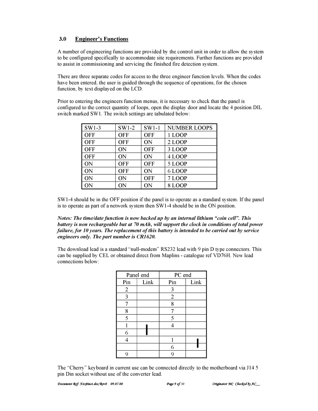
Prior to entering the engineers function menus, it is necessary to check that the panel is configured to the correct quantity of loops, open the display door and locate the 4 position DIL switch marked SW1. The switch settings are tabulated below:
NUMBER LOOPS | |||
OFF | OFF | OFF | 1 LOOP |
OFF | OFF | ON | 2 LOOP |
OFF | ON | OFF | 3 LOOP |
OFF | ON | ON | 4 LOOP |
ON | OFF | OFF | 5 LOOP |
ON | OFF | ON | 6 LOOP |
ON | ON | OFF | 7 LOOP |
ON | ON | ON | 8 LOOP |
Notes: The time/date function is now backed up by an internal lithium “coin cell”. This battery is non rechargeable but at 70 mAh, will support the clock in conditions of total power failure, for 10 years. The replacement of this battery is intended to be carried out by service engineers only. The part number is CR1620.
The download lead is a standard
Panel end | PC end | ||||
Pin | Link | Pin | Link | ||
2 |
|
| 3 |
|
|
3 |
|
| 2 |
|
|
7 |
|
| 8 |
|
|
8 |
|
| 7 |
|
|
5 |
|
| 5 |
|
|
1 |
|
| 4 |
|
|
|
|
|
| ||
6 |
|
|
|
|
|
|
|
|
|
|
|
4 |
|
| 1 |
|
|
|
|
|
| ||
|
|
| 6 |
|
|
|
|
|
|
| |
9 |
|
| 9 |
|
|
The “Cherry” keyboard in current use can be connected directly to the motherboard via J14 5 pin Din socket without use of the converter lead.
Document Ref: Nex8inst.doc/Rev0 09.07.00 | Page 9 of 30 | Originator MC Checked by AC__ |