M I N I A T U R E I N F R A R E D S E N S O R
+ | G | D | + | G | D |
12 | N | A | 12 | N | A |
V | D | T | V | D | T |
|
| A |
|
| A |
SENSOR INPUT
POWER STATUS
+12V DC
To unswitched
AC Outlet
IRP2+
MODEL IRP2+
IR
FLASHER
LEVEL
|
|
|
|
|
|
| DATA | ||
|
|
|
|
|
|
| OUT |
| |
|
| FLASHERS |
| G | D |
| |||
|
|
| A |
| |||||
|
| FULL |
| VAR |
| N | T |
| |
|
| + |
| + |
|
| D | A |
|
|
|
|
|
|
|
|
|
|
|
|
|
|
|
|
|
|
|
|
|
|
|
|
|
|
|
|
|
|
|
Room 1
Receiver
D + G A 12 N T V D A
SENSOR IN
Bare
Red ![]()
![]() Black
Black
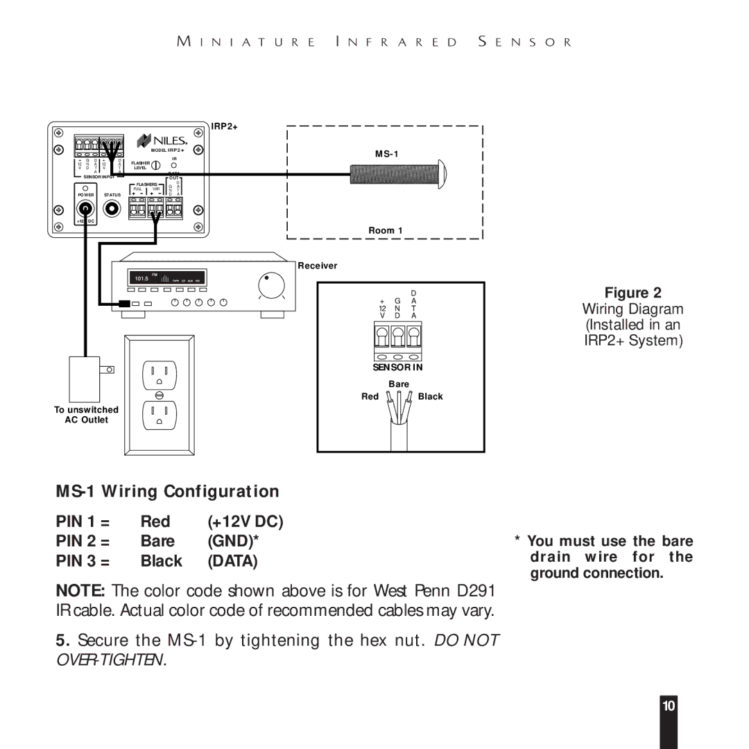
Figure 2
Wiring Diagram
(Installed in an
IRP2+ System)
MS-1 Wiring Configuration
PIN 1 = | Red | (+12V DC) |
PIN 2 = | Bare | (GND)* |
PIN 3 = | Black | (DATA) |
*You must use the bare drain wire for the ground connection.
NOTE: The color code shown above is for West Penn D291 IR cable. Actual color code of recommended cables may vary.
5.Secure the
10