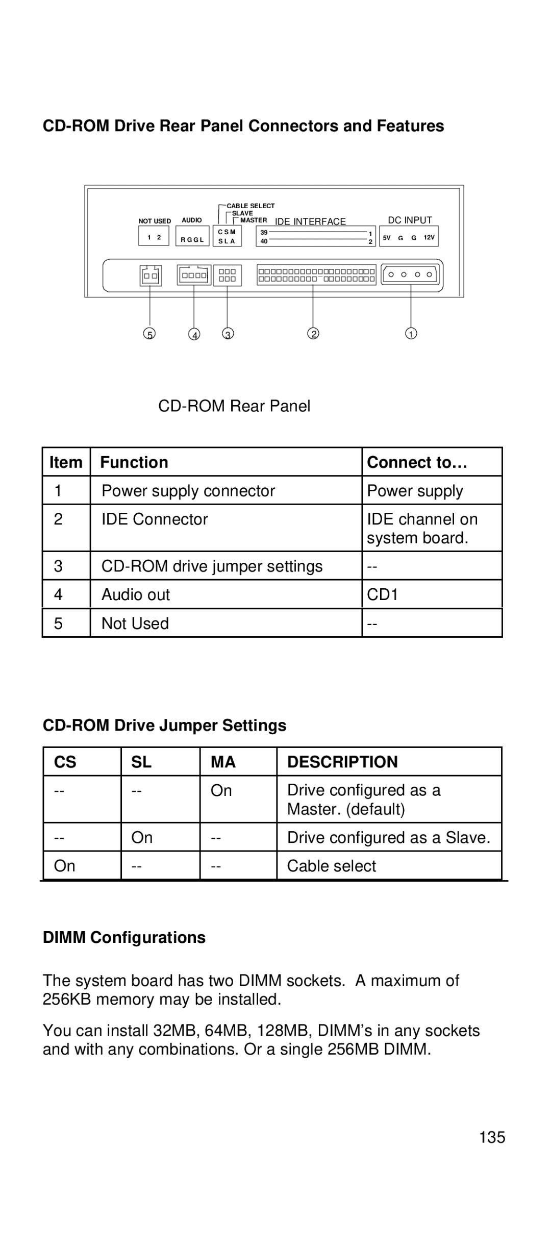
CD-ROM Drive Rear Panel Connectors and Features
|
| CABLE SELECT |
|
|
|
|
| |
|
| SLAVE | IDE INTERFACE |
| DC INPUT | |||
NOT USED | AUDIO |
| MASTER |
| ||||
1 2 | R G G L | C S M | 39 |
| 1 | 5V | G | G 12V |
S L A | 40 |
| 2 | |||||
|
|
|
|
| ||||
5 4 321
Item | Function | Connect to… |
|
|
|
1 | Power supply connector | Power supply |
|
|
|
2 | IDE Connector | IDE channel on |
|
| system board. |
|
|
|
3 | ||
|
|
|
4 | Audio out | CD1 |
|
|
|
5 | Not Used | |
|
|
|
CD-ROM Drive Jumper Settings
| CS | SL | MA | DESCRIPTION |
|
|
|
|
|
|
|
| On | Drive configured as a |
| ||
|
|
|
| Master. (default) |
|
|
|
|
|
|
|
| On | Drive configured as a Slave. |
| ||
|
|
|
|
|
|
| On | Cable select |
| ||
|
|
|
|
|
|
DIMM Configurations
The system board has two DIMM sockets. A maximum of 256KB memory may be installed.
You can install 32MB, 64MB, 128MB, DIMM’s in any sockets and with any combinations. Or a single 256MB DIMM.
135