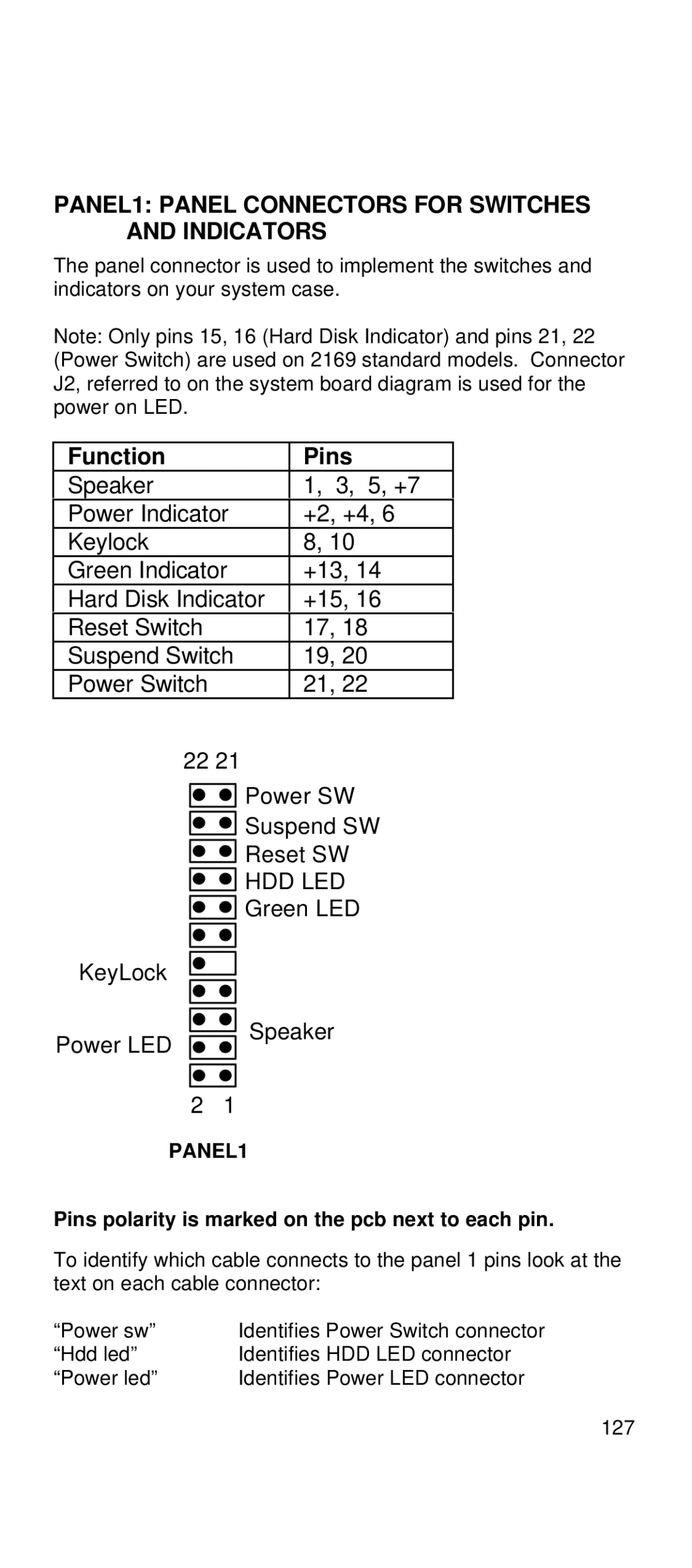
PANEL1: PANEL CONNECTORS FOR SWITCHES AND INDICATORS
The panel connector is used to implement the switches and indicators on your system case.
Note: Only pins 15, 16 (Hard Disk Indicator) and pins 21, 22 (Power Switch) are used on 2169 standard models. Connector J2, referred to on the system board diagram is used for the power on LED.
Function | Pins |
Speaker | 1, 3, 5, +7 |
Power Indicator | +2, +4, 6 |
Keylock | 8, 10 |
Green Indicator | +13, 14 |
Hard Disk Indicator | +15, 16 |
Reset Switch | 17, 18 |
Suspend Switch | 19, 20 |
Power Switch | 21, 22 |
22 21
![]()
![]()
![]()
![]() Power SW
Power SW
![]()
![]() Suspend SW
Suspend SW
![]()
![]() Reset SW
Reset SW
![]()
![]() HDD LED
HDD LED ![]()
![]() Green LED
Green LED
KeyLock
Power LED
Speaker
2 1
PANEL1
Pins polarity is marked on the pcb next to each pin.
To identify which cable connects to the panel 1 pins look at the text on each cable connector:
“Power sw” | Identifies Power Switch connector |
“Hdd led” | Identifies HDD LED connector |
“Power led” | Identifies Power LED connector |
127