Manuals
/
IBM
/
Computer Equipment
/
Computer Hardware
IBM
2169
manual
Models:
2169
1
133
157
157
Download
157 pages
14.51 Kb
130
131
132
133
134
135
136
137
Specs
Resume by Alarm
UR2 Duplex Mode DefaultL Half
Typematic Delay Msec
PNP/PCI Configuration Option
Error Symptoms Action/FRU
IBM PC Enhanced Diagnostics
Bios Setup Utility
Function Pins
Bios
Page 133
Image 133
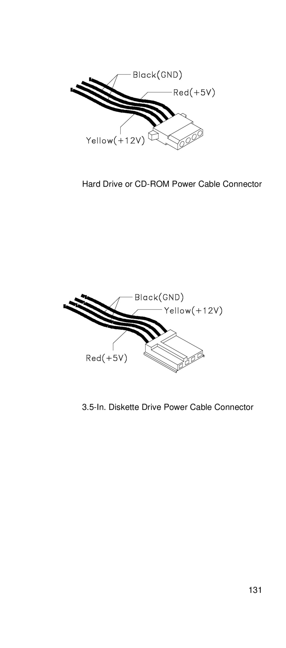
Hard Drive or
CD-ROM
Power Cable Connector
3.5-In.
Diskette Drive Power Cable Connector
131
Page 132
Page 134
Page 133
Image 133
Page 132
Page 134
Contents
Hardware Maintenance Manual for Service Level a
First Edition July
Contents
140
110
143
152
Voltage Supply Switch Settings
Page
To Connect To Disconnect
Do not
Page
Perigo
Para Conectar Para Desconectar
Não
Cuidado
Perigo
Page
Page
Page
Page
Page
Débranchez les câbles
Commencez pas
Branchez les cordons Dinterface des prises
Débranchez tous les
Page
Page
Vorsicht
Achtung
Kabel anschließen Kabel lösen
Page
Vorsicht
Per collegare Per scollegare
Pericolo
Attenzione
Quando è installata ununità CD-ROM, notare quanto segue
≥32 Kg ≥55Kg
Page
Page
Page
Instrucciones de conexión Desconexión
Peligro
Lo que no debe hacer
Peligro
Laser Compliance Statement
IBM
Trademarks
Preface
General Information
Product Overview
Introduction
Processors
Memory
Diskette Drive
Power Management
CD-ROM Drive
Multimedia
Internal Cabling
Power Supply
Modem Not all models
Keyboard
Interface
Hardware Interfaces
USB
Flash Bios Update Procedure
MTM
BIOS-contained Model Number and Serial Number
Working with the Setup Menus Starting the Setup Utility
Bios Setup Utility
Keys Function
Standard Cmos Features Option
Quick Power On Self Test
Advanced Bios Features Setup Option
Video
Halt On
Boot Other Device
First/Second/Third Boot Device
Boot Up Floppy Seek
Boot Up NumLock Status
Security Option
Typematic Rate Chars/Sec
OS Select For Dram 64 MB
Report No Diskette Drive for Win
Advanced Chipset Features Option
Integrated Peripherals Option
IDE HDD Block Mode
Hardware Reset
Uart Mode Select
UR2 Duplex Mode DefaultL Half
ECP Mode Use DMA Default
Parallel Port Mode
Midi Port IRQ Default
Pwron After PWR-Fail
Power Management Setup Option
HDD Power Down
Suspend Mode
Power On by Ring
Suspend Type
CPU Thermal Limit
Resume by Alarm
Board Thermal Limit
CPU Thermal-Throttling
Page
Reset Configuration Data
PNP/PCI Configuration Option
Resources Controlled By
PCI/VGA Palette Snoop
Frequency Control Option
PCI Health Status Option
Load Fail Safe Defaults Option
Load Optimized Defaults Option
Save And Exit Setup Option
Set Supervisor and User Passwords
Exit Without Saving Option
Erasing a lost or forgotten password clearing Cmos
Specifications
Operating Requirements
Special Tools
CheckProcedures
Introduction
IBM PC Enhanced Diagnostics
Product Recovery Program menu
Start
IBM PC Enhanced Memory Diagnostics
PC-Doctor’s Diagnostic Software
Enhanced Diagnostics download or diskette
Please Read the Following
Page
007
005
009
Index of Symptoms, Messages, Error Codes, or Beeps
Action/FRU Post Error Codes and Messages
Floppy Disks
Action/FRU
Device. Then reboot the system
Action/FRU Beeps
System Board
Error Symptoms Action/FRU Processor
Page
Hard Disk Drive
Error Symptoms Action/FRU
CD-ROM Drive
Real-Time Clock
Parallel
Diagnostics programs
Other Problems
Page
003
Factory-Installed Storage Devices
005
Page
002
Factory-Installed Modem Card Start
Modem adapter functions normally End
Audio Not Supported by Diagnostics Program
006
004
008
Memory Start
CD-ROM Drive Start
Keyboard Start
Mouse Start
011
010
Power Supply Start
Page
Replace the on/off switch cable assembly
Monitor
Is the Screen READABLE? YES, Read AHEAD. NO, GO to Step
Undetermined Problems
105
Diagnostic Aids
Introduction
Power-On Self Test
Diagnostics Tools
Performing a partial or full recovery
Submenu Selections
Diagnostics Program Features
Page
Repair Information
Removals and Replacements of machine type
Identifying the Parts of the System Unit
Page
Top Cover
Adapter Cards Installing Adapter Cards
Removing Adapter Cards
Diskette Drive
To remove CD-ROM Drive
Hard Disk Drive
System Board
Memory Dimm
122
Parts/Test Point Locations
Introduction
Layout of system board of the machine type
Component Description
FP1
LED2
Sense
Pins polarity is marked on the pcb next to each pin
Function Pins
Replacing the system battery
Power Supply Cable Connector Specifications
Pin Function Color
Main Output Pin Assignment
Page
Factory-Installed Modem Card Connector Functions Connect to…
Factory-Installed Modem Card Layout
Hard Disk Quantum Jumper Settings Locations
In. Hard Disk Drive Jumper Locations & Settings
CD-ROM Emergency-exit
CD-ROM Drive Jumper Settings
CD-ROM Drive Rear Panel Connectors and Features
Dimm Configurations
Function Connect to…
Parallel Port Signals Pin Signal Name
Serial Port Signals Pin Signal Name
Keyboard Port Signals Pin Signal Name
Mouse Port Signals Pin Signal Name
Diskette Drive Cable Connector Signals Pin Signal Name
IDE Cable Connector Signals Pin Signal Name
141
Safety Inspection Guide
General Guidelines
Page
Parts Catalog
Part Catalog of machine type
Assembly 1 System Unit Asm-Index FRU Number Description
14F0032 Power Cord UK/HK/Singapore
Not Shown
Page
FRU Number Description
Assembly 3 CD-ROM, Modem Card
60H6027 Modem Phone Cable Adapter Denmark
Assembly 4 Keyboard and Mouse
Palm Rest Hungarian
Appendix A. Online Support Information
Index
Bios
Check Procedure, 99 ctor Specifications, 125 Error Symptoms
Top
Page
Image
Contents