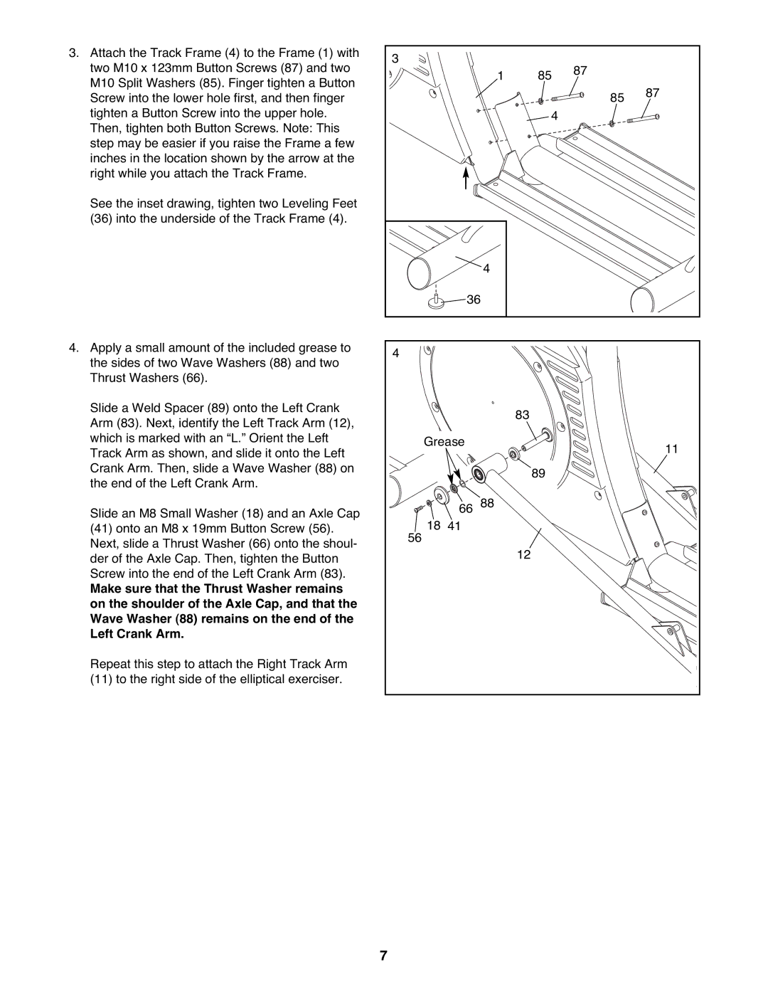
3. Attach the Track Frame (4) to the Frame (1) with | 3 |
|
|
|
two M10 x 123mm Button Screws (87) and two |
| 87 |
| |
1 | 85 |
| ||
M10 Split Washers (85). Finger tighten a Button |
|
| ||
|
|
| 87 | |
Screw into the lower hole first, and then finger |
|
| 85 | |
|
|
| ||
tighten a Button Screw into the upper hole. |
| 4 |
|
|
Then, tighten both Button Screws. Note: This |
|
|
|
|
step may be easier if you raise the Frame a few |
|
|
|
|
inches in the location shown by the arrow at the |
|
|
|
|
right while you attach the Track Frame. |
|
|
|
|
See the inset drawing, tighten two Leveling Feet (36) into the underside of the Track Frame (4).
|
| 4 |
| 36 | |
4. Apply a small amount of the included grease to | 4 |
|
the sides of two Wave Washers (88) and two |
| |
|
| |
Thrust Washers (66). |
|
|
Slide a Weld Spacer (89) onto the Left Crank |
| 83 |
Arm (83). Next, identify the Left Track Arm (12), |
| |
|
| |
which is marked with an “L.” Orient the Left | Grease | 11 |
Track Arm as shown, and slide it onto the Left |
| |
|
| |
Crank Arm. Then, slide a Wave Washer (88) on |
| 89 |
the end of the Left Crank Arm. |
| |
|
| |
Slide an M8 Small Washer (18) and an Axle Cap | 66 | 88 |
18 41 |
| |
(41) onto an M8 x 19mm Button Screw (56). |
| |
Next, slide a Thrust Washer (66) onto the shoul- | 56 |
|
| 12 | |
der of the Axle Cap. Then, tighten the Button |
| |
|
| |
Screw into the end of the Left Crank Arm (83). |
|
|
Make sure that the Thrust Washer remains |
|
|
on the shoulder of the Axle Cap, and that the |
|
|
Wave Washer (88) remains on the end of the |
|
|
Left Crank Arm. |
|
|
Repeat this step to attach the Right Track Arm |
|
|
(11) to the right side of the elliptical exerciser. |
|
|
7
