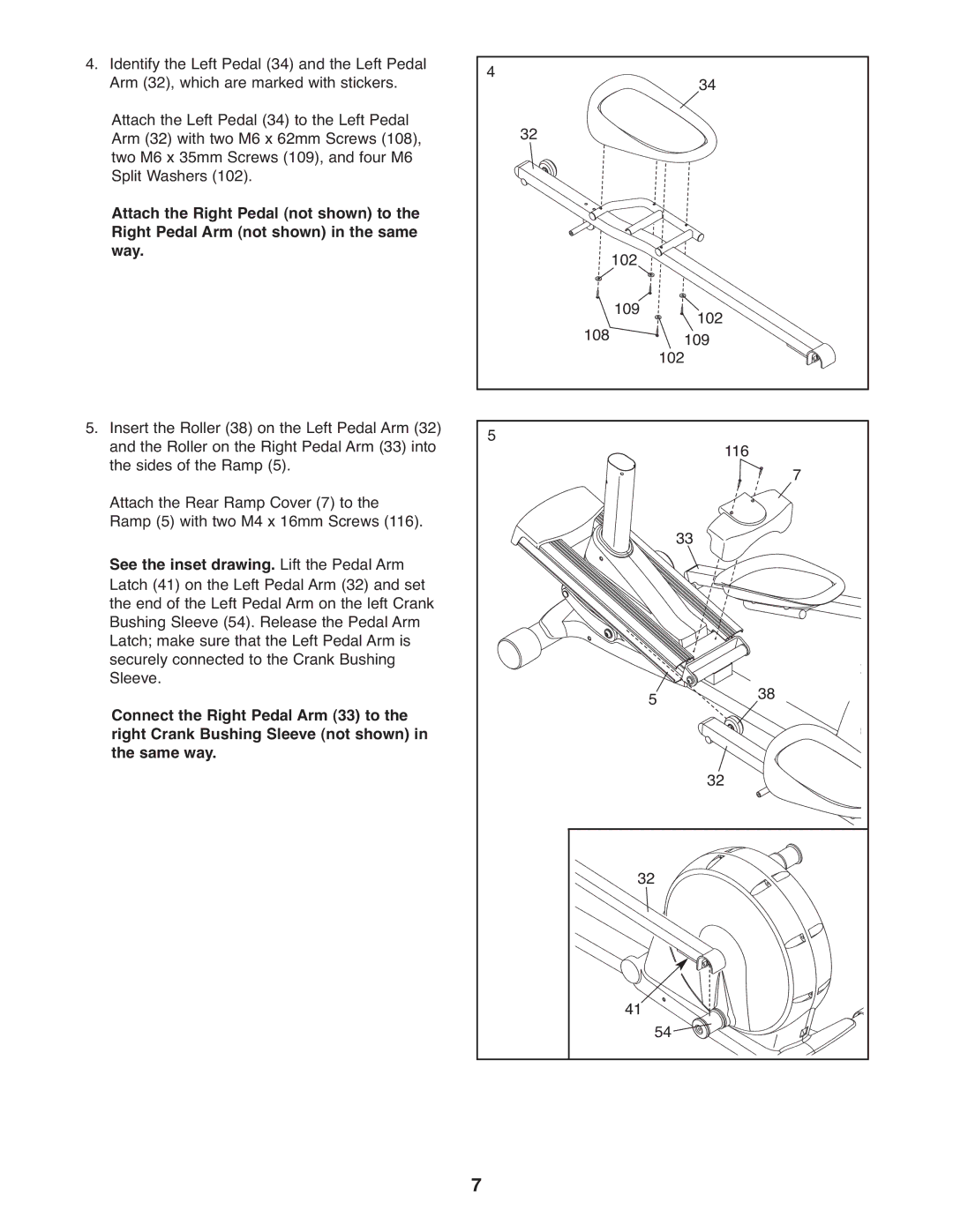
4. Identify the Left Pedal (34) and the Left Pedal | 4 |
| 34 |
|
|
Arm (32), which are marked with stickers. |
|
|
| ||
Attach the Left Pedal (34) to the Left Pedal | 32 |
|
|
|
|
Arm (32) with two M6 x 62mm Screws (108), |
|
|
|
| |
two M6 x 35mm Screws (109), and four M6 |
|
|
|
|
|
Split Washers (102). |
|
|
|
|
|
Attach the Right Pedal (not shown) to the |
|
|
|
|
|
Right Pedal Arm (not shown) in the same |
| 102 |
|
|
|
way. |
|
|
|
| |
| 108 | 109 | 102 |
|
|
|
| 102109 |
|
| |
5. Insert the Roller (38) on the Left Pedal Arm (32) | 5 |
|
| 116 |
|
and the Roller on the Right Pedal Arm (33) into |
|
| 7 | ||
the sides of the Ramp (5). |
|
|
|
| |
Attach the Rear Ramp Cover (7) to the |
|
|
|
|
|
Ramp (5) with two M4 x 16mm Screws (116). |
|
| 33 |
|
|
See the inset drawing. Lift the Pedal Arm |
|
|
|
| |
|
|
|
|
| |
Latch (41) on the Left Pedal Arm (32) and set |
|
|
|
|
|
the end of the Left Pedal Arm on the left Crank |
|
|
|
|
|
Bushing Sleeve (54). Release the Pedal Arm |
|
|
|
|
|
Latch; make sure that the Left Pedal Arm is |
|
|
|
|
|
securely connected to the Crank Bushing |
|
|
|
|
|
Sleeve. |
|
| 5 |
| 38 |
Connect the Right Pedal Arm (33) to the |
|
|
| ||
right Crank Bushing Sleeve (not shown) in |
|
|
|
|
|
the same way. |
|
| 32 |
|
|
|
|
|
|
| |
|
| 32 |
|
| |
|
| 41 | 54 |
|
|
| 7 |
|
|
|
|