Assembly Option B
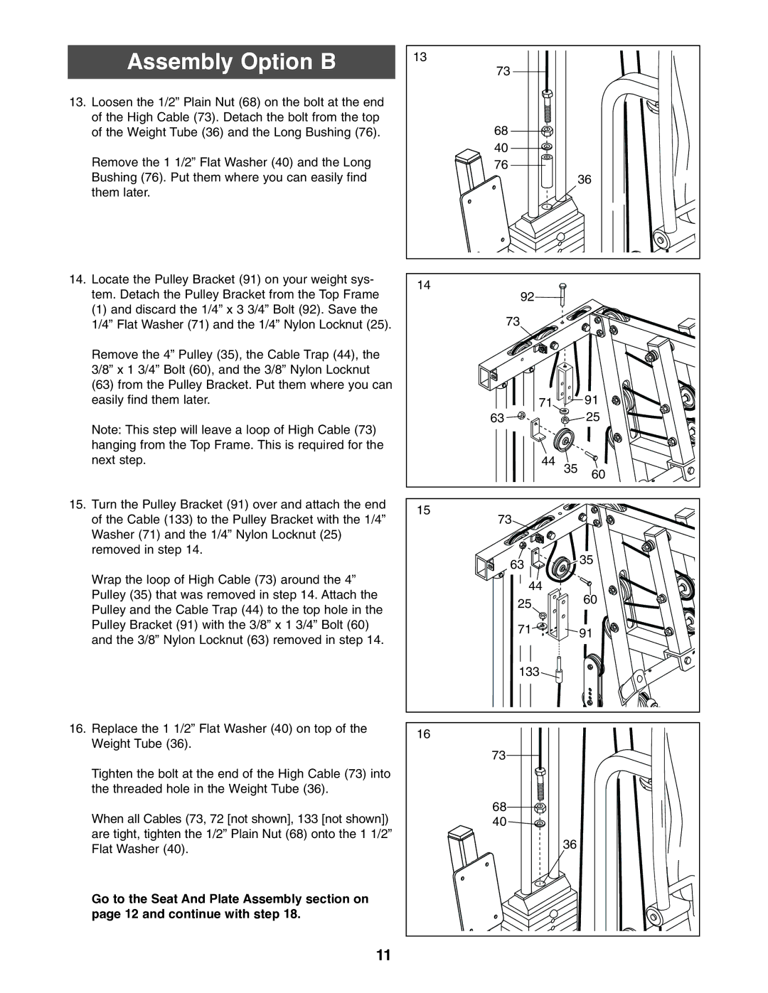
13.Loosen the 1/2” Plain Nut (68) on the bolt at the end of the High Cable (73). Detach the bolt from the top of the Weight Tube (36) and the Long Bushing (76).
Remove the 1 1/2” Flat Washer (40) and the Long Bushing (76). Put them where you can easily find them later.
14.Locate the Pulley Bracket (91) on your weight sys- tem. Detach the Pulley Bracket from the Top Frame
(1) and discard the 1/4” x 3 3/4” Bolt (92). Save the 1/4” Flat Washer (71) and the 1/4” Nylon Locknut (25).
Remove the 4” Pulley (35), the Cable Trap (44), the 3/8” x 1 3/4” Bolt (60), and the 3/8” Nylon Locknut
(63)from the Pulley Bracket. Put them where you can easily find them later.
Note: This step will leave a loop of High Cable (73) hanging from the Top Frame. This is required for the next step.
15.Turn the Pulley Bracket (91) over and attach the end of the Cable (133) to the Pulley Bracket with the 1/4” Washer (71) and the 1/4” Nylon Locknut (25) removed in step 14.
Wrap the loop of High Cable (73) around the 4” Pulley (35) that was removed in step 14. Attach the Pulley and the Cable Trap (44) to the top hole in the Pulley Bracket (91) with the 3/8” x 1 3/4” Bolt (60) and the 3/8” Nylon Locknut (63) removed in step 14.
16.Replace the 1 1/2” Flat Washer (40) on top of the Weight Tube (36).
Tighten the bolt at the end of the High Cable (73) into the threaded hole in the Weight Tube (36).
When all Cables (73, 72 [not shown], 133 [not shown]) are tight, tighten the 1/2” Plain Nut (68) onto the 1 1/2” Flat Washer (40).
Go to the Seat And Plate Assembly section on page 12 and continue with step 18.
13 |
|
|
73 |
|
|
68 |
|
|
40 |
|
|
76 |
|
|
|
| 36 |
14 |
|
|
92 |
|
|
73 |
|
|
71 |
| 91 |
63 |
| 25 |
44 | 35 | 60 |
|
| |
15 |
|
|
73 |
|
|
63 |
| 35 |
|
| |
44 |
| 60 |
25 |
| |
|
| |
71 |
| 91 |
|
| |
133 |
|
|
16 |
|
|
73 |
|
|
68 |
|
|
40 |
|
|
| 36 |
|
11
