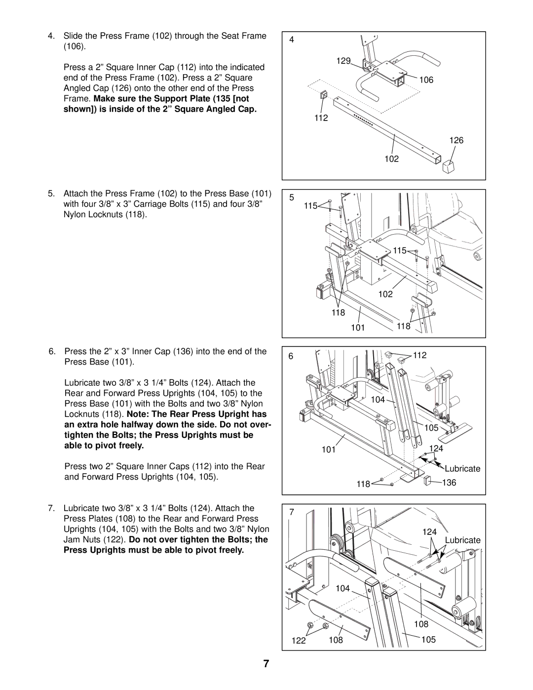
4.Slide the Press Frame (102) through the Seat Frame (106).
Press a 2” Square Inner Cap (112) into the indicated end of the Press Frame (102). Press a 2” Square Angled Cap (126) onto the other end of the Press Frame. Make sure the Support Plate (135 [not shown]) is inside of the 2” Square Angled Cap.
5.Attach the Press Frame (102) to the Press Base (101) with four 3/8” x 3” Carriage Bolts (115) and four 3/8” Nylon Locknuts (118).
6.Press the 2” x 3” Inner Cap (136) into the end of the Press Base (101).
Lubricate two 3/8” x 3 1/4” Bolts (124). Attach the Rear and Forward Press Uprights (104, 105) to the Press Base (101) with the Bolts and two 3/8” Nylon Locknuts (118). Note: The Rear Press Upright has an extra hole halfway down the side. Do not over- tighten the Bolts; the Press Uprights must be able to pivot freely.
Press two 2” Square Inner Caps (112) into the Rear and Forward Press Uprights (104, 105).
7.Lubricate two 3/8” x 3 1/4” Bolts (124). Attach the Press Plates (108) to the Rear and Forward Press Uprights (104, 105) with the Bolts and two 3/8” Nylon Jam Nuts (122). Do not over tighten the Bolts; the
Press Uprights must be able to pivot freely.
4 |
|
|
| 129 |
|
|
| 106 |
| 112 |
|
|
| 126 |
|
| 102 |
5 |
|
|
115 |
| |
|
| 115 |
|
| 102 |
| 118 |
|
| 101 | 118 |
6 |
| 112 |
|
| 104 |
|
| 105 |
| 101 | 124 |
|
| Lubricate |
| 118 | 136 |
7 |
|
|
|
| 124 |
|
| Lubricate |
| 104 |
|
|
| 108 |
122 | 108 | 105 |
7
