Frame Assembly
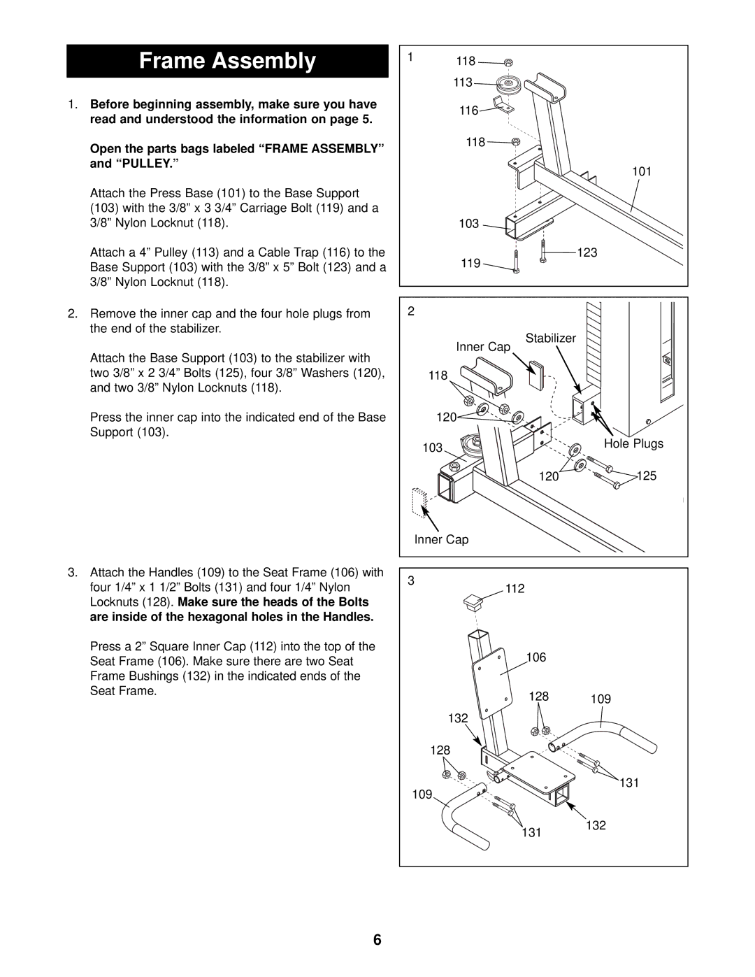
1.Before beginning assembly, make sure you have read and understood the information on page 5.
Open the parts bags labeled “FRAME ASSEMBLY” and “PULLEY.”
Attach the Press Base (101) to the Base Support
(103)with the 3/8” x 3 3/4” Carriage Bolt (119) and a 3/8” Nylon Locknut (118).
Attach a 4” Pulley (113) and a Cable Trap (116) to the Base Support (103) with the 3/8” x 5” Bolt (123) and a 3/8” Nylon Locknut (118).
2.Remove the inner cap and the four hole plugs from the end of the stabilizer.
Attach the Base Support (103) to the stabilizer with two 3/8” x 2 3/4” Bolts (125), four 3/8” Washers (120), and two 3/8” Nylon Locknuts (118).
Press the inner cap into the indicated end of the Base Support (103).
3.Attach the Handles (109) to the Seat Frame (106) with four 1/4” x 1 1/2” Bolts (131) and four 1/4” Nylon Locknuts (128). Make sure the heads of the Bolts are inside of the hexagonal holes in the Handles.
Press a 2” Square Inner Cap (112) into the top of the Seat Frame (106). Make sure there are two Seat Frame Bushings (132) in the indicated ends of the Seat Frame.
1 | 118 |
|
|
|
|
| |
| 113 |
|
|
| 116 |
|
|
| 118 |
|
|
|
|
| 101 |
| 103 |
|
|
| 119 |
| 123 |
|
|
| |
2 |
|
|
|
|
| Stabilizer |
|
| Inner Cap |
| |
| 118 |
|
|
| 120 |
|
|
| 103 |
| Hole Plugs |
|
|
| |
|
| 120 | 125 |
Inner Cap |
|
| |
3 |
| 112 |
|
|
|
| |
|
| 106 |
|
|
| 128 | 109 |
| 132 |
|
|
| 128 |
|
|
109 |
| 131 | |
|
| ||
|
| 131 | 132 |
|
|
| |
6
