1010, 1050, 1100 specifications
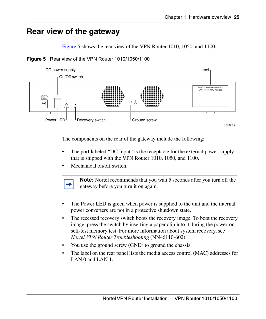
Nortel Networks 1100 series is a suite of innovative communication solutions designed to enhance voice and data capabilities for businesses of all sizes. Originally launched as part of Nortel’s extensive portfolio, the 1100 series focuses on delivering advanced technologies that ensure reliable and scalable performance.One of the most prominent features of the Nortel Networks 1100 series is its robust voice over IP (VoIP) capabilities. This allows businesses to make and receive calls over the internet, significantly reducing traditional telephony costs while enhancing call quality. The series supports multiple codecs, enabling users to choose the most suitable audio quality based on their bandwidth availability.
The Nortel 1100 series also boasts a user-friendly interface, making it accessible for employees at all levels of technical expertise. The phones feature a high-resolution display and programmable soft keys, allowing users to customize their experience and access frequently used features with ease.
Another characteristic presented in the Nortel 1100 series is its support for a wide range of applications, including unified communications. This integration streamlines various communication channels, allowing users to seamlessly switch between voice, video, and instant messaging. Consequently, collaboration is greatly enhanced, improving overall productivity within organizations.
In terms of security, the Nortel 1100 series implements industry-standard protocols to ensure all communications are encrypted and protected from potential threats. This focus on security is crucial in today's digital landscape, where data breaches can have significant ramifications for both businesses and stakeholders.
Moreover, the Nortel 1100 series is designed for scalability. Businesses can start with a few units and easily expand their communication solutions as their operations grow. This flexibility makes it an attractive option for both small businesses and larger enterprises.
Power over Ethernet (PoE) capability is another feature of the Nortel 1100 series, simplifying installation by eliminating the need for separate power cables. This streamlining not only reduces installation costs but also provides a neat and organized workspace.
In summary, the Nortel Networks 1100 series stands out for its blend of VoIP capabilities, user-friendly design, application support, strong security measures, scalability, and PoE functionality. These characteristics make it an appealing choice for companies looking to modernize their communication infrastructure while ensuring reliability and efficiency.

