.
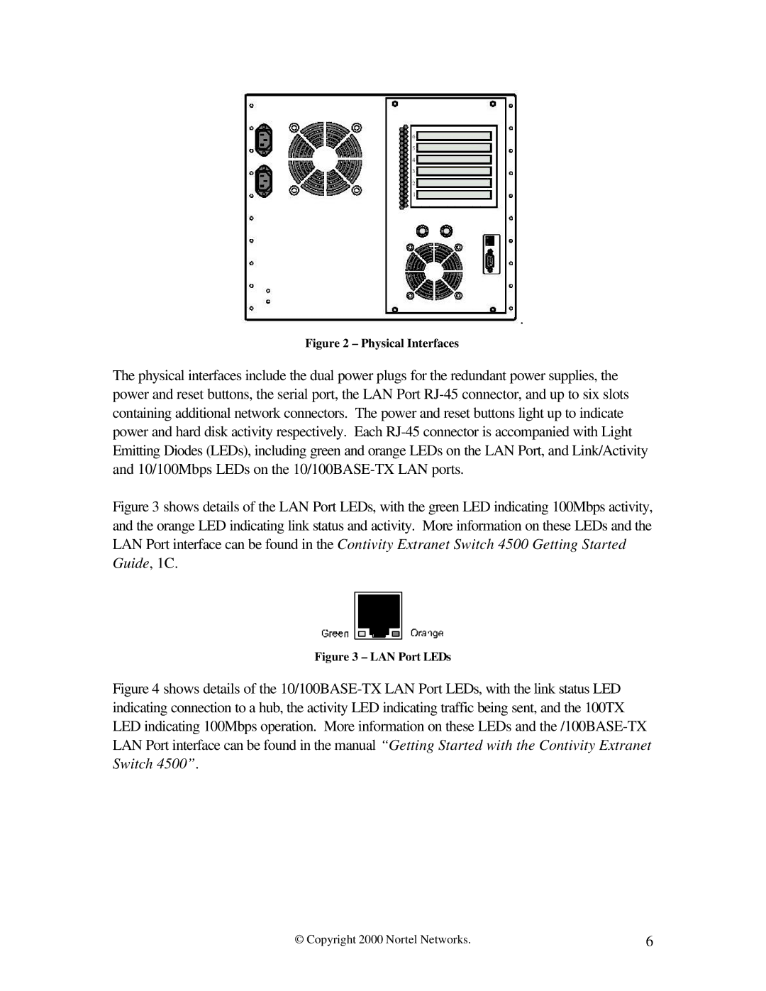
Figure 2 – Physical Interfaces
The physical interfaces include the dual power plugs for the redundant power supplies, the power and reset buttons, the serial port, the LAN Port
Figure 3 shows details of the LAN Port LEDs, with the green LED indicating 100Mbps activity, and the orange LED indicating link status and activity. More information on these LEDs and the LAN Port interface can be found in the Contivity Extranet Switch 4500 Getting Started Guide, 1C.
Figure 3 – LAN Port LEDs
Figure 4 shows details of the 10/100BASE-TX LAN Port LEDs, with the link status LED indicating connection to a hub, the activity LED indicating traffic being sent, and the 100TX LED indicating 100Mbps operation. More information on these LEDs and the /100BASE-TX LAN Port interface can be found in the manual “Getting Started with the Contivity Extranet Switch 4500”.
© Copyright 2000 Nortel Networks. | 6 |