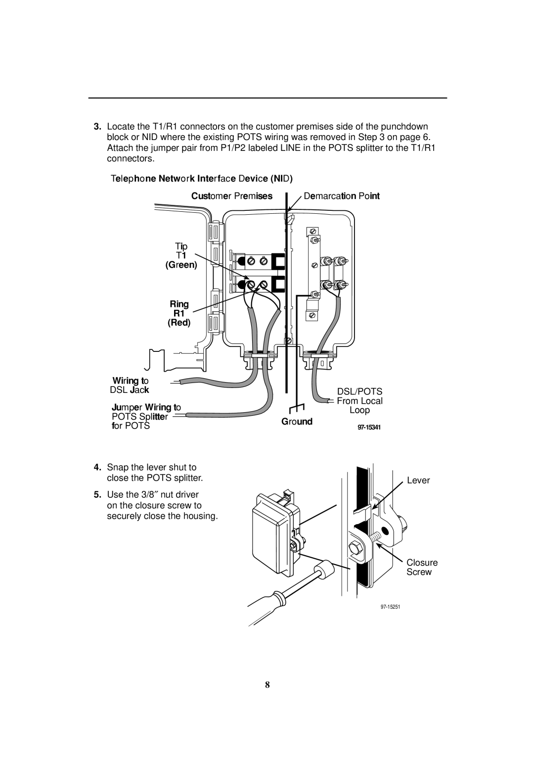
3.Locate the T1/R1 connectors on the customer premises side of the punchdown block or NID where the existing POTS wiring was removed in Step 3 on page 6. Attach the jumper pair from P1/P2 labeled LINE in the POTS splitter to the T1/R1 connectors.
Telephone Network Interface Device (NID) |
| ||
Customer Premises | Demarcation Point | ||
Tip |
|
| |
T1 |
|
| |
(Green) |
|
| |
Ring |
|
| |
R1 |
|
| |
(Red) |
|
| |
Wiring to |
|
| |
DSL Jack |
| DSL/POTS | |
Jumper Wiring to |
| From Local | |
| Loop | ||
POTS Splitter |
| ||
Ground |
| ||
for POTS | |||
| |||
4.Snap the lever shut to close the POTS splitter.
5.Use the 3/8″ nut driver on the closure screw to securely close the housing.
Lever
Closure
Screw
8
