SECTION TWO — Installing the transducer
•the path for running the transducer’s cable is reasonably
•water turbulence and noise are minimal, decreasing the amount of bubbles passing over the transducer face
•the transducer isn’t behind hull irregularities or near eroding paint; both indicate areas subject to turbulence
•the transducer is as far as possible from the engine or propellers, and inboard of the lifting strakes
•the transducer always remains submerged and parallel to the water surface
•the transducer is easily accessible from inside the vessel for adjust- ments and maintenance
•the transducer’s ultrasonic beams aren’t obstructed by the keel, pro- peller shafts, or any other part of the vessel
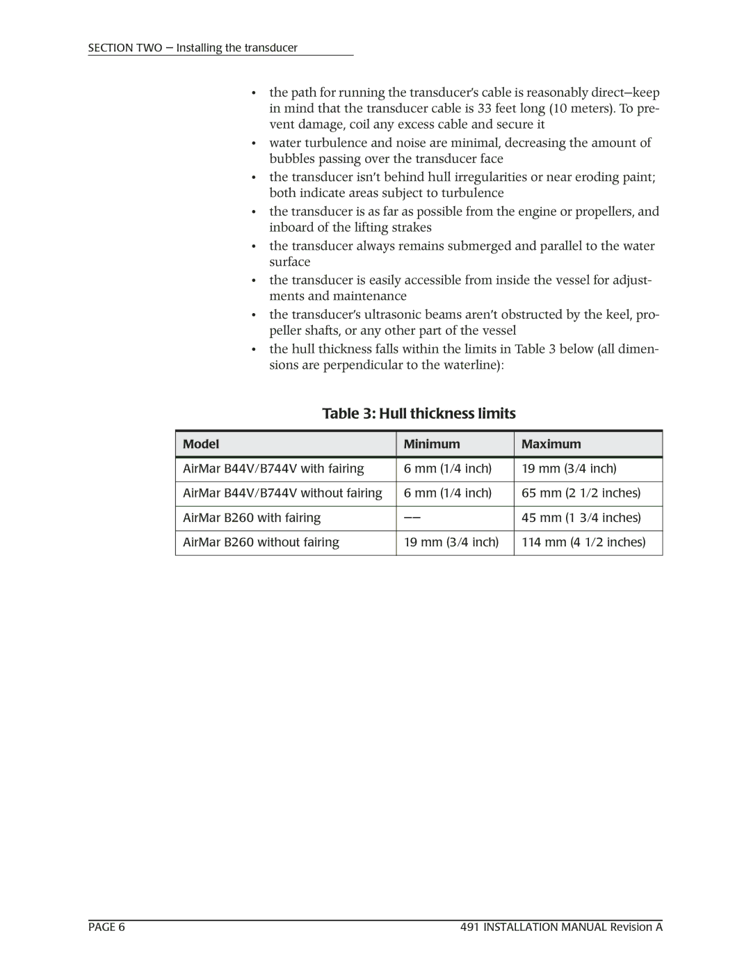
•the hull thickness falls within the limits in Table 3 below (all dimen- sions are perpendicular to the waterline):
Table 3: Hull thickness limits
Model | Minimum | Maximum |
|
|
|
AirMar B44V/B744V with fairing | 6 mm (1/4 inch) | 19 mm (3/4 inch) |
|
|
|
AirMar B44V/B744V without fairing | 6 mm (1/4 inch) | 65 mm (2 1/2 inches) |
|
|
|
AirMar B260 with fairing | 45 mm (1 3/4 inches) | |
|
|
|
AirMar B260 without fairing | 19 mm (3/4 inch) | 114 mm (4 1/2 inches) |
|
|
|
PAGE 6 | 491 INSTALLATION MANUAL Revision A |