SECTION TWO — Installing the transducer
3˚ incline ![]() angle
angle
1/3 aft
LWL
(Load Waterline Length)
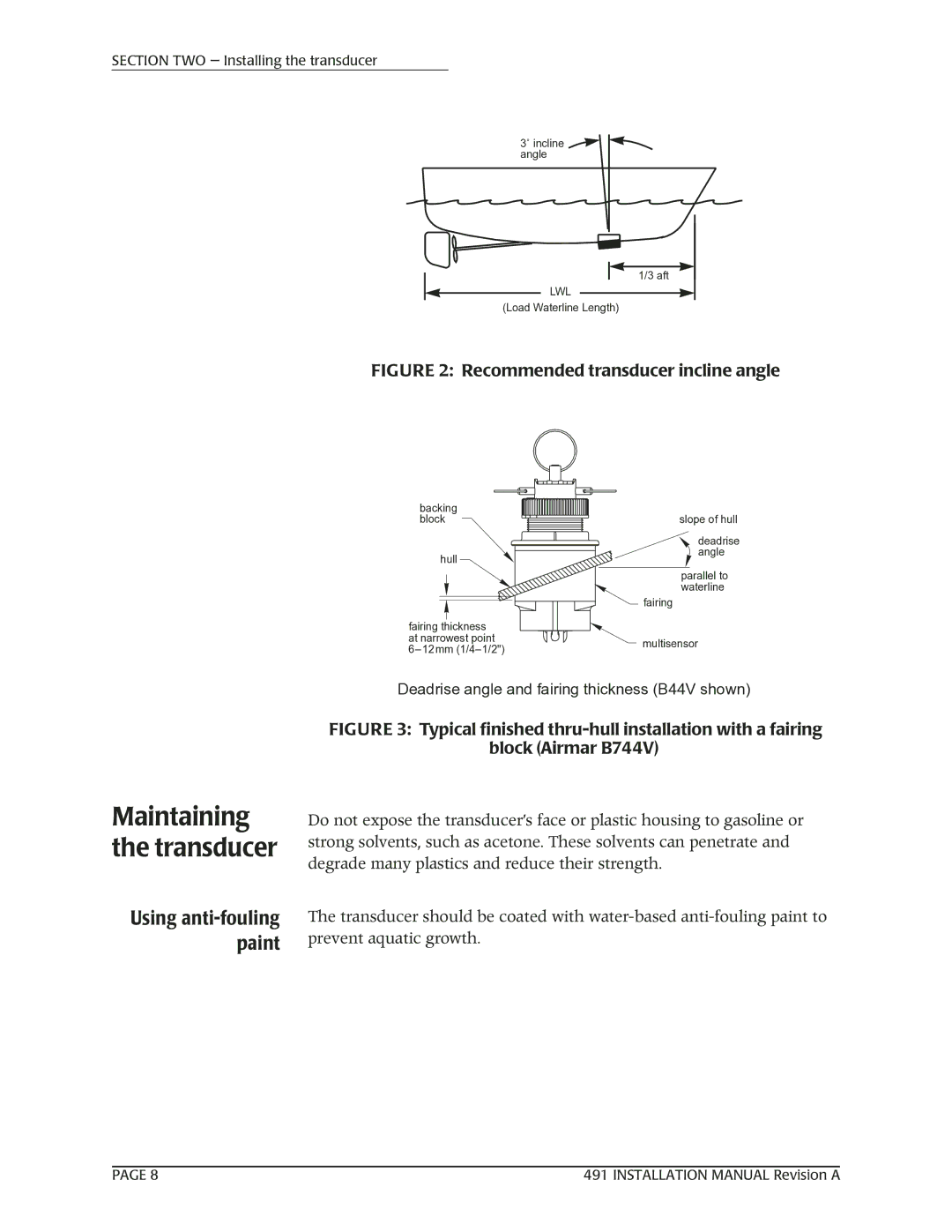
FIGURE 2: Recommended transducer incline angle
backing |
| |
block | slope of hull | |
| deadrise | |
hull | angle | |
| ||
| parallel to | |
| waterline | |
| fairing | |
fairing thickness |
| |
at narrowest point | multisensor | |
|
Deadrise angle and fairing thickness (B44V shown)
Maintaining the transducer
Using anti-fouling paint
FIGURE 3: Typical finished thru-hull installation with a fairing
block (Airmar B744V)
Do not expose the transducer’s face or plastic housing to gasoline or strong solvents, such as acetone. These solvents can penetrate and degrade many plastics and reduce their strength.
The transducer should be coated with
PAGE 8 | 491 INSTALLATION MANUAL Revision A |
