The Natural Way to Look at a Computer™
Retrofit Kit
Assembly Instructions
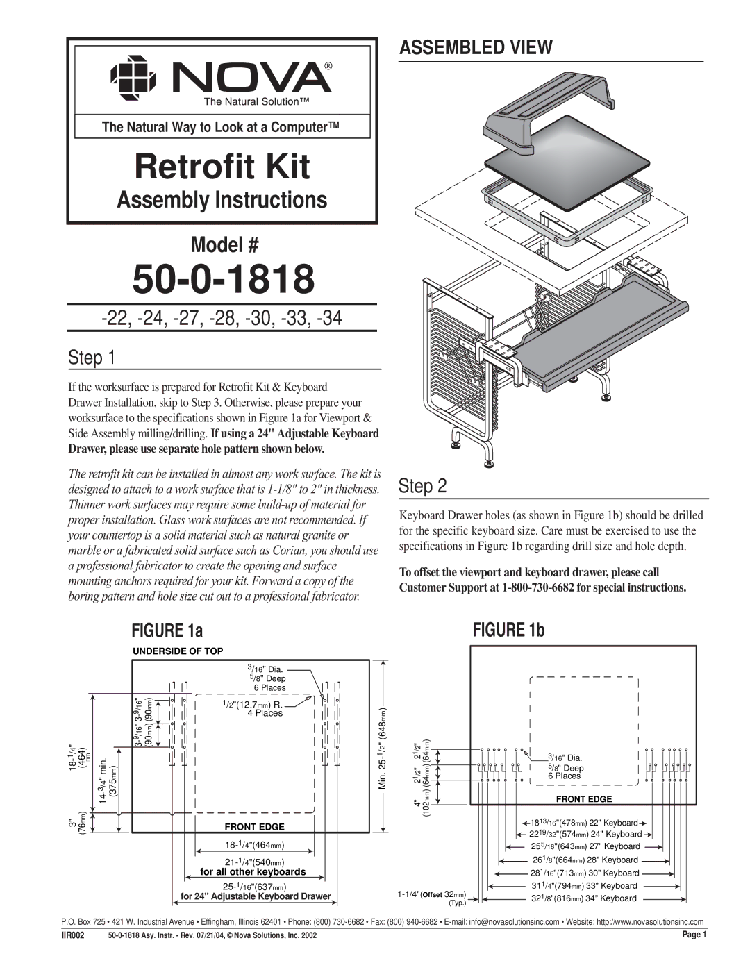
ASSEMBLED VIEW
Model #
50-0-1818
-22, -24, -27, -28, -30, -33, -34
Step 1
If the worksurface is prepared for Retrofit Kit & Keyboard Drawer Installation, skip to Step 3. Otherwise, please prepare your worksurface to the specifications shown in Figure 1a for Viewport & Side Assembly milling/drilling. If using a 24" Adjustable Keyboard
Drawer, please use separate hole pattern shown below.
The retrofit kit can be installed in almost any work surface. The kit is designed to attach to a work surface that is
FIGURE 1a
|
|
|
| UNDERSIDE OF TOP | ||
|
|
|
|
|
| 3/16" Dia. |
|
|
|
|
|
| 5/8" Deep |
|
|
|
|
|
| 6 Places |
|
|
|
| " ) | mm(648) | |
|
|
|
| 9 | )(90mm | |
|
|
|
| / 16 |
| 1/2"(12.7mm) R. |
|
|
|
| - |
| 4 Places |
(464) mm | )(375mm | 9 | (90mm | |||
|
|
|
| 163/" |
|
|
/4" |
|
|
|
|
| /2" |
1 |
| . |
|
|
| 1 |
|
| /4" min |
|
|
|
|
|
| 3 |
|
|
|
|
3" | ) |
|
|
|
|
|
(76mm |
|
|
|
| FRONT EDGE | |
|
|
|
|
|
| |
|
|
|
|
|
| |
for all other keyboards
for 24" Adjustable Keyboard Drawer
Step 2
Keyboard Drawer holes (as shown in Figure 1b) should be drilled for the specific keyboard size. Care must be exercised to use the specifications in Figure 1b regarding drill size and hole depth.
To offset the viewport and keyboard drawer, please call
Customer Support at
|
| FIGURE 1b | |
/2" | (64mm) |
| |
1 | 3/16" Dia. | ||
2 | |||
2" | mm) | 5/8" Deep | |
/ | 6 Places | ||
1 | |||
2 | (64 |
| |
4" | (102mm) | FRONT EDGE | |
1813/16"(478mm) 22" Keyboard | |||
|
| ||
|
| 2219/32"(574mm) 24" Keyboard | |
|
| 255/16"(643mm) 27" Keyboard | |
|
| 261/8"(664mm) 28" Keyboard | |
|
| 281/16"(713mm) 30" Keyboard | |
311/4"(794mm) 33" Keyboard | |||
321/8"(816mm) 34" Keyboard | |||
| (Typ.) | ||
|
| ||
P.O. Box 725 • 421 W. Industrial Avenue • Effingham, Illinois 62401 • Phone: (800)
IIR002 | Page 1 |
