INSTALLATION (Continued)
Connecting the Optional Electronic Chime Module
MODELS IA-28 OR IA-29
1.Connect wires from door pushbuttons - front, rear and side - to chime module.
2.Refer to the instructions packaged with the chime module for complete wiring information.
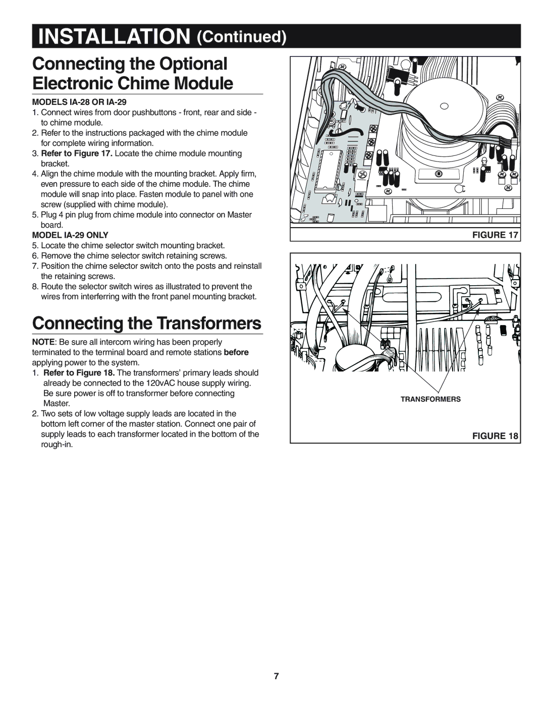
3.Refer to Figure 17. Locate the chime module mounting bracket.
4.Align the chime module with the mounting bracket. Apply firm, even pressure to each side of the chime module. The chime module will snap into place. Fasten module to panel with one screw (supplied with chime module).
5.Plug 4 pin plug from chime module into connector on Master board.
MODEL IA-29 ONLY
5.Locate the chime selector switch mounting bracket.
6.Remove the chime selector switch retaining screws.
7.Position the chime selector switch onto the posts and reinstall the retaining screws.
8.Route the selector switch wires as illustrated to prevent the wires from interferring with the front panel mounting bracket.
Connecting the Transformers
NOTE: Be sure all intercom wiring has been properly terminated to the terminal board and remote stations before applying power to the system.
1.Refer to Figure 18. The transformers’ primary leads should already be connected to the 120vAC house supply wiring. Be sure power is off to transformer before connecting Master.
2.Two sets of low voltage supply leads are located in the bottom left corner of the master station. Connect one pair of supply leads to each transformer located in the bottom of the
FIGURE 17 |
TRANSFORMERS
FIGURE 18
7
