BMG7011 and BMG7012 User’s Guide Rev. 1.9
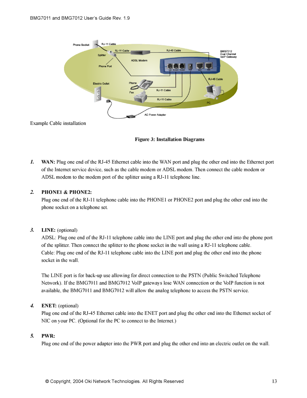
Example Cable installation
Figure 3: Installation Diagrams
1.WAN: Plug one end of the RJ-45 Ethernet cable into the WAN port and plug the other end into the Ethernet port of the Internet service device, such as the cable modem or ADSL modem. Then connect the cable modem or ADSL modem to the modem port of the splitter using a RJ-11 telephone line.
2.PHONE1 & PHONE2:
Plug one end of the RJ-11 telephone cable into the PHONE1 or PHONE2 port and plug the other end into the phone socket on a telephone set.
3.LINE: (optional)
ADSL: Plug one end of the RJ-11 telephone cable into the LINE port and plug the other end into the phone port of the splitter. Then connect the splitter to the phone socket in the wall using a RJ-11 telephone cable.
Cable: Plug one end of the RJ-11 telephone cable into the LINE port and plug the other end into the phone socket in the wall.
The LINE port is for back-up use allowing for direct connection to the PSTN (Public Switched Telephone Network). If the BMG7011 and BMG7012 VoIP gateways lose WAN connection or the VoIP function is not available, the BMG7011 and BMG7012 will allow the analog telephone to access the PSTN service.
4.ENET: (optional)
Plug one end of the RJ-45 Ethernet cable into the ENET port and plug the other end into the Ethernet socket of NIC on your PC. (Optional for the PC to connect to the Internet.)
5.PWR:
Plug one end of the power adapter into the PWR port and plug the other end into an electric outlet on the wall.
© Copyright, 2004 Oki Network Technologies. All Rights Reserved | 13 |