Technical Description
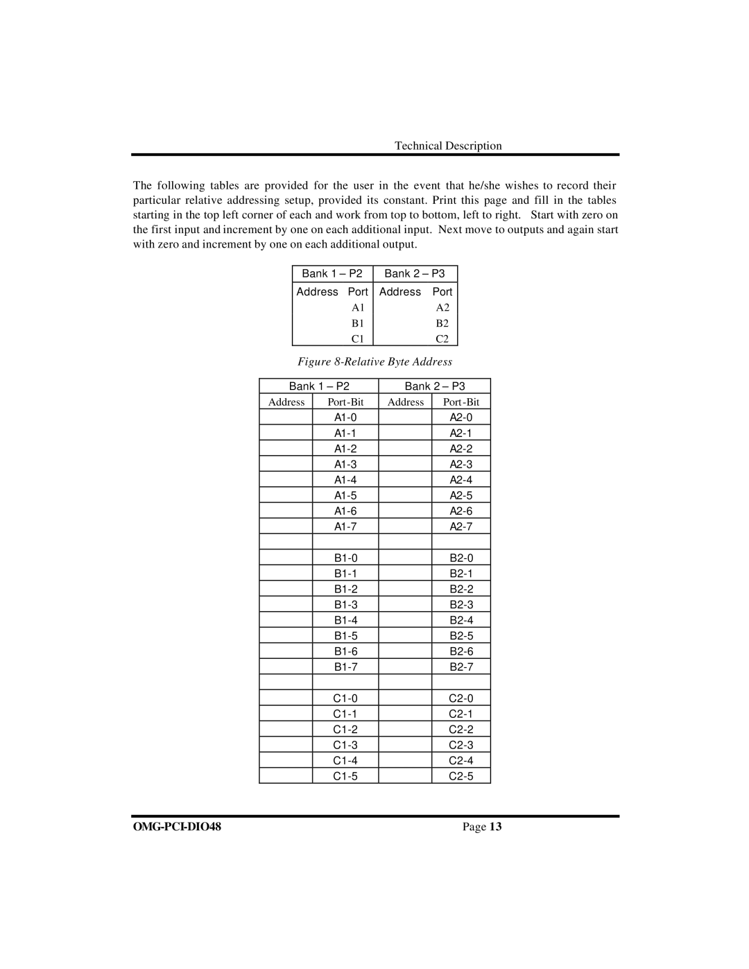
The following tables are provided for the user in the event that he/she wishes to record their particular relative addressing setup, provided its constant. Print this page and fill in the tables starting in the top left corner of each and work from top to bottom, left to right. Start with zero on the first input and increment by one on each additional input. Next move to outputs and again start with zero and increment by one on each additional output.
Bank 1 – P2 | Bank 2 – P3 |
|
|
Address Port | Address Port |
A1 | A2 |
B1 | B2 |
C1 | C2 |
Figure 8-Relative Byte Address
Bank 1 – P2 | Bank 2 – P3 | ||
Address | Port | Address | Port |
|
| ||
|
| ||
|
| ||
|
| ||
|
| ||
|
| ||
|
| ||
|
| ||
|
|
|
|
|
| ||
|
| ||
|
| ||
|
| ||
|
| ||
|
| ||
|
| ||
|
| ||
|
|
|
|
|
| ||
|
| ||
|
| ||
|
| ||
|
| ||
|
| ||
| Page 13 |