9.2 ADDRESS
The required channel is selected by four address lines.
The operating voltages are:
Logical "1" 5V < Vi < 60V
Logical "0" 0V < Vi< 0.5V
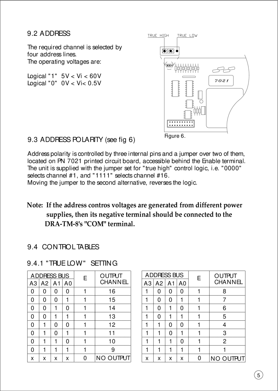
9.3 ADDRESS POLARITY (see fig 6) | Figure 6. |
|
Address polarity is controlled by three internal pins and a jumper over two of them, located on PN 7021 printed circuit board, accessible behind the Enable terminal. The unit is supplied with the jumper set for "true high" control logic, i.e. "0000" selects channel #1, and "1111" selects channel #16.
Moving the jumper to the second alternative, reverses the logic.
Note: If the address contros voltages are generated from different power supplies, then its negative terminal should be connected to the
9.4CONTROL TABLES 9.4.1 "TRUE LOW" SETTING
ADDRESS BUS | E | OUTPUT | |||
A3 | A2 | A1 | A0 |
| CHANNEL |
0 | 0 | 0 | 0 | 1 | 16 |
0 | 0 | 0 | 1 | 1 | 15 |
0 | 0 | 1 | 0 | 1 | 14 |
0 | 0 | 1 | 1 | 1 | 13 |
0 | 1 | 0 | 0 | 1 | 12 |
0 | 1 | 0 | 1 | 1 | 11 |
0 | 1 | 1 | 0 | 1 | 10 |
0 | 1 | 1 | 1 | 1 | 9 |
x | x | x | x | 0 | NO OUTPUT |
| ADDRESS BUS | E | OUTPUT | |||
| A3 | A2 | A1 | A0 |
| CHANNEL |
1 | 0 | 0 | 0 | 1 | 8 | |
1 | 0 | 0 | 1 | 1 | 7 | |
1 | 0 | 1 | 0 | 1 | 6 | |
1 | 0 | 1 | 1 | 1 | 5 | |
1 | 1 | 0 | 0 | 1 | 4 | |
1 | 1 | 0 | 1 | 1 | 3 | |
| 1 | 1 | 1 | 0 | 1 | 2 |
| 1 | 1 | 1 | 1 | 1 | 1 |
| x | x | x | x | 0 | NO OUTPUT |
5