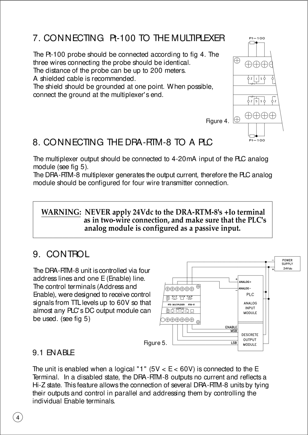
7. CONNECTING Pt-100 TO THE MULTIPLEXER
The Pt-100 probe should be connected according to fig 4. The three wires connecting the probe should be identical.
The distance of the probe can be up to 200 meters. A shielded cable is recommended.
The shield should be grounded at one point. When possible, connect the ground at the multiplexer's end.
Figure 4.
8. CONNECTING THE DRA-RTM-8 TO A PLC
The multiplexer output should be connected to 4-20mA input of the PLC analog module (see fig 5).
The DRA-RTM-8 multiplexer generates the output current, therefore the PLC analog module should be configured for four wire transmitter connection.
WARNING: NEVER apply 24Vdc to the DRA-RTM-8's +Io terminal as in two-wire connection, and make sure that the PLC's analog module is configured as a passive input.
9. CONTROL
The DRA-RTM-8 unit is controlled via four address lines and one E (Enable) line. The control terminals (Address and Enable), were designed to receive control signals from TTL levels up to 60V so that almost any PLC's DC output module can be used. (see fig 5)
Figure 5.
9.1 ENABLE
The unit is enabled when a logical "1" (5V < E < 60V) is connected to the E Terminal. In a disabled state, the DRA-RTM-8 outputs no current and reflects a Hi-Z state. This feature allows the connection of several DRA-RTM-8 units by tying their outputs and control in parallel and addressing them by controlling the individual Enable terminals.