i. Change the address to the next channel to be calibrated. j. Repeat steps b to h
* The calibrator is set according to DIN 43760
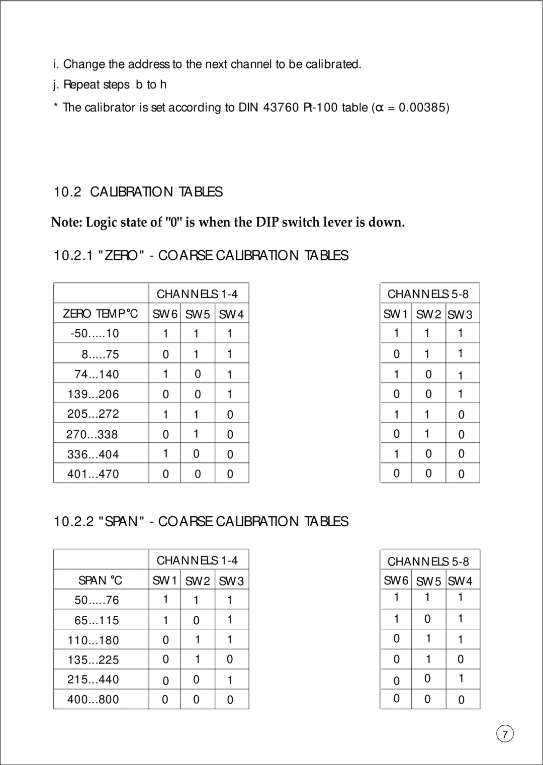
10.2 CALIBRATION TABLES
Note: Logic state of "0" is when the DIP switch lever is down.
10.2.1 "ZERO" - COARSE CALIBRATION TABLES
| CHANNELS | ||
ZERO TEMP OC | SW6 | SW5 | SW4 |
1 | 1 | 1 | |
|
|
|
|
8.....75 | 0 | 1 | 1 |
74...140 | 1 | 0 | 1 |
139...206 | 0 | 0 | 1 |
205...272 | 1 | 1 | 0 |
270...338 | 0 | 1 | 0 |
336...404 | 1 | 0 | 0 |
401...470 | 0 | 0 | 0 |
|
|
|
|
CHANNELS
SW1 | SW2 | SW3 |
1 | 1 | 1 |
|
|
|
0 | 1 | 1 |
|
|
|
1 | 0 | 1 |
0 | 0 | 1 |
|
|
|
1 | 1 | 0 |
0 | 1 | 0 |
1 | 0 | 0 |
|
|
|
0 | 0 | 0 |
|
|
|
10.2.2 "SPAN" - COARSE CALIBRATION TABLES
| CHANNELS | ||
SPAN OC | SW1 | SW2 | SW3 |
50.....76 | 1 | 1 | 1 |
65...115 | 1 | 0 | 1 |
110...180 | 0 | 1 | 1 |
135...225 | 0 | 1 | 0 |
215...440 | 0 | 0 | 1 |
400...800 | 0 | 0 | 0 |
|
|
|
|
CHANNELS
SW6 | SW5 | SW4 |
1 | 1 | 1 |
|
|
|
1 | 0 | 1 |
|
|
|
0 | 1 | 1 |
|
|
|
0 | 1 | 0 |
|
|
|
0 | 0 | 1 |
0 | 0 | 0 |
|
|
|
7