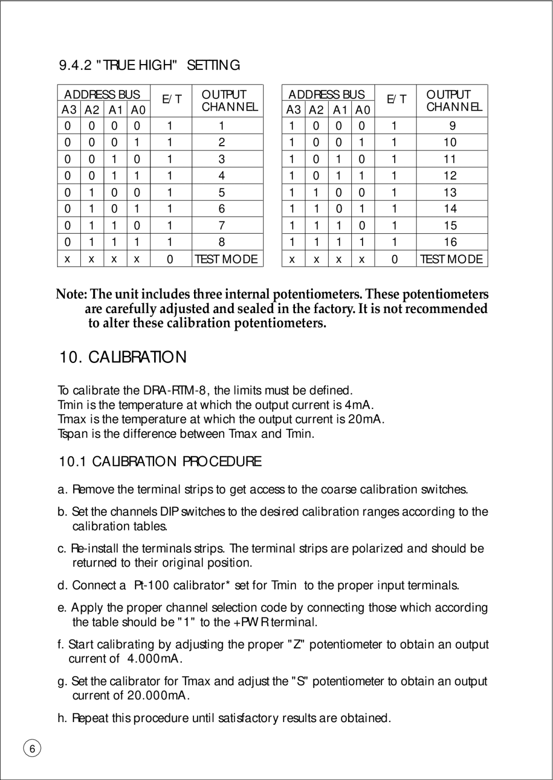
9.4.2 "TRUE HIGH" SETTING
ADDRESS BUS | E/T | OUTPUT | |||
A3 | A2 | A1 | A0 |
| CHANNEL |
0 | 0 | 0 | 0 | 1 | 1 |
0 | 0 | 0 | 1 | 1 | 2 |
0 | 0 | 1 | 0 | 1 | 3 |
0 | 0 | 1 | 1 | 1 | 4 |
0 | 1 | 0 | 0 | 1 | 5 |
0 | 1 | 0 | 1 | 1 | 6 |
0 | 1 | 1 | 0 | 1 | 7 |
0 | 1 | 1 | 1 | 1 | 8 |
x | x | x | x | 0 | TEST MODE |
| ADDRESS BUS | E/T | OUTPUT | |||
| A3 | A2 | A1 | A0 |
| CHANNEL |
1 | 0 | 0 | 0 | 1 | 9 | |
1 | 0 | 0 | 1 | 1 | 10 | |
1 | 0 | 1 | 0 | 1 | 11 | |
1 | 0 | 1 | 1 | 1 | 12 | |
1 | 1 | 0 | 0 | 1 | 13 | |
1 | 1 | 0 | 1 | 1 | 14 | |
| 1 | 1 | 1 | 0 | 1 | 15 |
| 1 | 1 | 1 | 1 | 1 | 16 |
| x | x | x | x | 0 | TEST MODE |
Note: The unit includes three internal potentiometers. These potentiometers are carefully adjusted and sealed in the factory. It is not recommended to alter these calibration potentiometers.
10. CALIBRATION
To calibrate the
10.1CALIBRATION PROCEDURE
a.Remove the terminal strips to get access to the coarse calibration switches.
b.Set the channels DIP switches to the desired calibration ranges according to the calibration tables.
c.
d.Connect a
e.Apply the proper channel selection code by connecting those which according the table should be "1" to the +PWR terminal.
f.Start calibrating by adjusting the proper "Z" potentiometer to obtain an output current of 4.000mA.
g.Set the calibrator for Tmax and adjust the "S" potentiometer to obtain an output current of 20.000mA.
h.Repeat this procedure until satisfactory results are obtained.
6