11. MULTIDROP CONFIGURATION
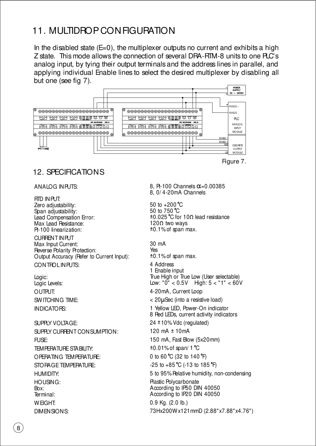
In the disabled state (E=0), the multiplexer outputs no current and exhibits a high Z state. This mode allows the connection of several
12. SPECIFICATIONS
ANALOG INPUTS:
RTD INPUT:
Zero adjustability: Span adjustability:
Lead Compensation Error: Max Lead Resistance:
CURRENT INPUT
Max Input Current: Reverse Polarity Protection:
Output Accuracy (Refer to Current Input):
CONTROL INPUTS:
Logic:
Logic Levels:
OUTPUT:
SWITCHING TIME:
INDICATORS:
SUPPLY VOLTAGE:
SUPPLY CURRENT CONSUMPTION: FUSE:
TEMPERATURE STABILITY: OPERATING TEMPERATURE: STORAGE TEMPERATURE: HUMIDITY:
HOUSING:
Box:
Terminal:
WEIGHT:
DIMENSIONS:
ANALOG +
ANALOG -
PLC
ANALOG
INPUT
MODULE
ENABLE 1
ENABLE 2
MSB DISCRETE
OUTPUT
LSB MODULE
Figure 7.
8,
8,
50 to +200 oC
50 to 750 oC
![]() 0.025 oC for 10W lead resistance 120W two ways
0.025 oC for 10W lead resistance 120W two ways
![]() 0.1% of span max.
0.1% of span max.
30mA
Yes
![]() 0.1% of span max.
0.1% of span max.
4 Address
1 Enable input
True High or True Low (User selectable) Low: "0" < 0.5V High: 5 < "1" < 60V
< 20mSec (into a resistive load)
1 Yellow LED,
8 Red LEDs, current activity indicators
24 ![]() 10% Vdc (regulated)
10% Vdc (regulated)
120 mA ![]() 10mA
10mA
150 mA, Fast Blow (5x20mm)
![]() 0.01% of span/1 oC
0.01% of span/1 oC
0 to 60 oC (32 to 140 oF)
5 to 95% Relative humidity,
Plastic Polycarbonate According to IP50 DIN 40050 According to IP20 DIN 40050
0.9 Kg. (2.0 lb.)
73Hx200Wx121mmD (2.88"x7.88"x4.76")
8