VI. General Assembly Instructions
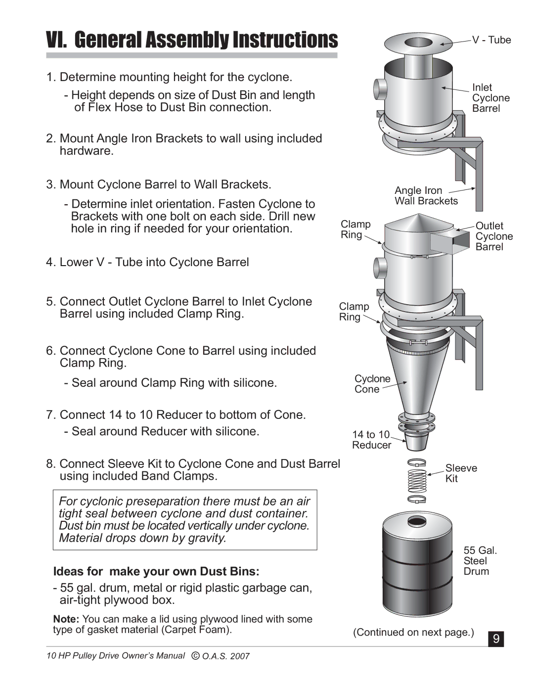
1. Determine mounting height for the cyclone.
- Height depends on size of Dust Bin and length of Flex Hose to Dust Bin connection.
2.Mount Angle Iron Brackets to wall using included hardware.
3.Mount Cyclone Barrel to Wall Brackets.
- Determine inlet orientation. Fasten Cyclone to |
| |
Brackets with one bolt on each side. Drill new | Clamp | |
hole in ring if needed for your orientation. | ||
Ring | ||
| ||
4. Lower V - Tube into Cyclone Barrel |
|
![]()
![]() V - Tube
V - Tube
Inlet
Cyclone
Barrel
Angle Iron
Wall Brackets
![]()
![]()
![]() Outlet
Outlet
Cyclone
Barrel
5.Connect Outlet Cyclone Barrel to Inlet Cyclone Barrel using included Clamp Ring.
6.Connect Cyclone Cone to Barrel using included Clamp Ring.
-Seal around Clamp Ring with silicone.
Clamp |
Ring |
Cyclone
Cone ![]()
7.Connect 14 to 10 Reducer to bottom of Cone.
-Seal around Reducer with silicone.
8.Connect Sleeve Kit to Cyclone Cone and Dust Barrel using included Band Clamps.
For cyclonic preseparation there must be an air tight seal between cyclone and dust container. Dust bin must be located vertically under cyclone. Material drops down by gravity.
Ideas for make your own Dust Bins:
-55 gal. drum, metal or rigid plastic garbage can,
Note: You can make a lid using plywood lined with some type of gasket material (Carpet Foam).
14 to 10 |
Reducer |
Sleeve
![]() Kit
Kit
55 Gal.
Steel
Drum
(Continued on next page.) | 9 |
|
10 HP Pulley Drive Owner’s Manual c O.A.S. 2007