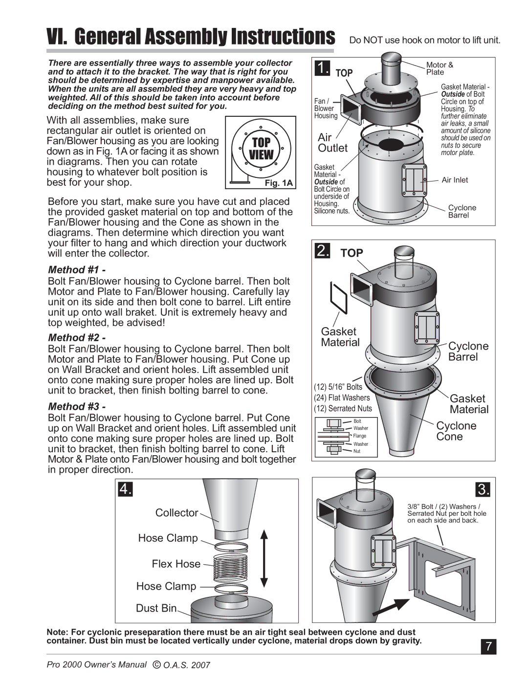
VI. General Assembly Instructions Do NOT use hook on motor to lift unit.
There are essentially three ways to assemble your collector | 1. TOP | Motor & | |||
and to attach it to the bracket. The way that is right for you | Plate | ||||
should be determined by expertise and manpower available. |
|
| Gasket Material - | ||
When the units are all assembled they are very heavy and top |
|
| |||
weighted. All of this should be taken into account before | Fan / |
| Outside of Bolt | ||
| Circle on top of | ||||
deciding on the method best suited for you. |
|
| |||
| Blower |
| Housing. To | ||
With all assemblies, make sure |
| Housing |
| further eliminate | |
|
|
| air leaks, a small | ||
rectangular air outlet is oriented on |
| Air |
| amount of silicone | |
Fan/Blower housing as you are looking | TOP |
| should be used on | ||
Outlet | nuts to secure | ||||
down as in Fig. 1A or facing it as shown | VIEW | motor plate. | |||
in diagrams. Then you can rotate |
| Gasket |
|
| |
housing to whatever bolt position is |
|
|
| ||
| Material - |
| Air Inlet | ||
best for your shop. | Fig. 1A | Outside of | |||
|
| Bolt Circle on |
| ||
Before you start, make sure you have cut and placed | underside of |
| |||
Housing. |
| Cyclone | |||
the provided gasket material on top and bottom of the | Silicone nuts. | ||||
Barrel | |||||
Fan/Blower housing and the Cone as shown in the |
|
|
| ||
diagrams. Then determine which direction you want |
|
|
| ||
your filter to hang and which direction your ductwork | 2. | TOP |
| ||
will enter the collector. |
|
| |||
Method #1 - |
|
|
|
| |
Bolt Fan/Blower housing to Cyclone barrel. Then bolt |
|
|
| ||
Motor and Plate to Fan/Blower housing. Carefully lay |
|
|
| ||
unit on its side and then bolt cone to barrel. Lift entire |
|
|
| ||
unit up onto wall braket. Unit is extremely heavy and |
|
|
| ||
top weighted, be advised! |
| Gasket |
| ||
Method #2 - |
|
| |||
| Material | Cyclone | |||
Bolt Fan/Blower housing to Cyclone barrel. Then bolt | |||||
|
| ||||
Motor and Plate to Fan/Blower housing. Put Cone up |
|
| Barrel | ||
on Wall Bracket and orient holes. Lift assembled unit |
|
|
| ||
onto cone making sure proper holes are lined up. Bolt | (12) 5/16” Bolts |
| |||
unit to bracket, then finish bolting barrel to cone. | Gasket | ||||
Method #3 - |
| (24) Flat Washers | |||
| (12) Serrated Nuts | Material | |||
Bolt Fan/Blower housing to Cyclone barrel. Put Cone |
| Bolt | Cyclone | ||
up on Wall Bracket and orient holes. Lift assembled unit |
| Washer | |||
onto cone making sure proper holes are lined up. Bolt |
| Flange | Cone | ||
| Washer | ||||
unit to bracket, then finish bolting barrel to cone. Lift |
|
| |||
| Nut |
| |||
Motor & Plate onto Fan/Blower housing and bolt together |
|
|
| ||
in proper direction. |
|
|
|
| |
4. |
|
|
| 3. | |
Collector |
|
|
| 3/8” Bolt / (2) Washers / | |
|
|
| Serrated Nut per bolt hole | ||
|
|
|
| on each side and back. | |
Hose Clamp
Flex Hose
Hose Clamp
Dust Bin
Note: For cyclonic preseparation there must be an air tight seal between cyclone and dust |
|
container. Dust bin must be located vertically under cyclone, material drops down by gravity. | 7 |
|
Pro 2000 Owner’s Manual c O.A.S. 2007