Contents
Before Using Your DVD Changer Receiver
DVD Changer Receiver
Important Safeguards
Defeat the safety purpose of the polarized plug
If the appliance has been dropped or damaged in any way,
Wall or Ceiling Mounting The appliance should be
Precautions
Precautions
Table of Contents
Other Features
Features
Receiver Features
DVD/CD Changer Features
RCA 3-pin Audio/Video connection cable
Supplied Accessories
MP3 Compatibility Information
Structure of the Disc Content
Playable Discs
About Video CDs
Do not touch the playback side of the disc
Cleaning Discs
Handling Discs
Storing Discs
Front panel
Index to Parts and Controls
Display
Index to Parts and Controls
Remote controller
Preset 5/∞ buttons
# Setup buttons AUDIO/SP Setup button 24
SW Mode button
SEND/LEARN indicator 56
Rear panel
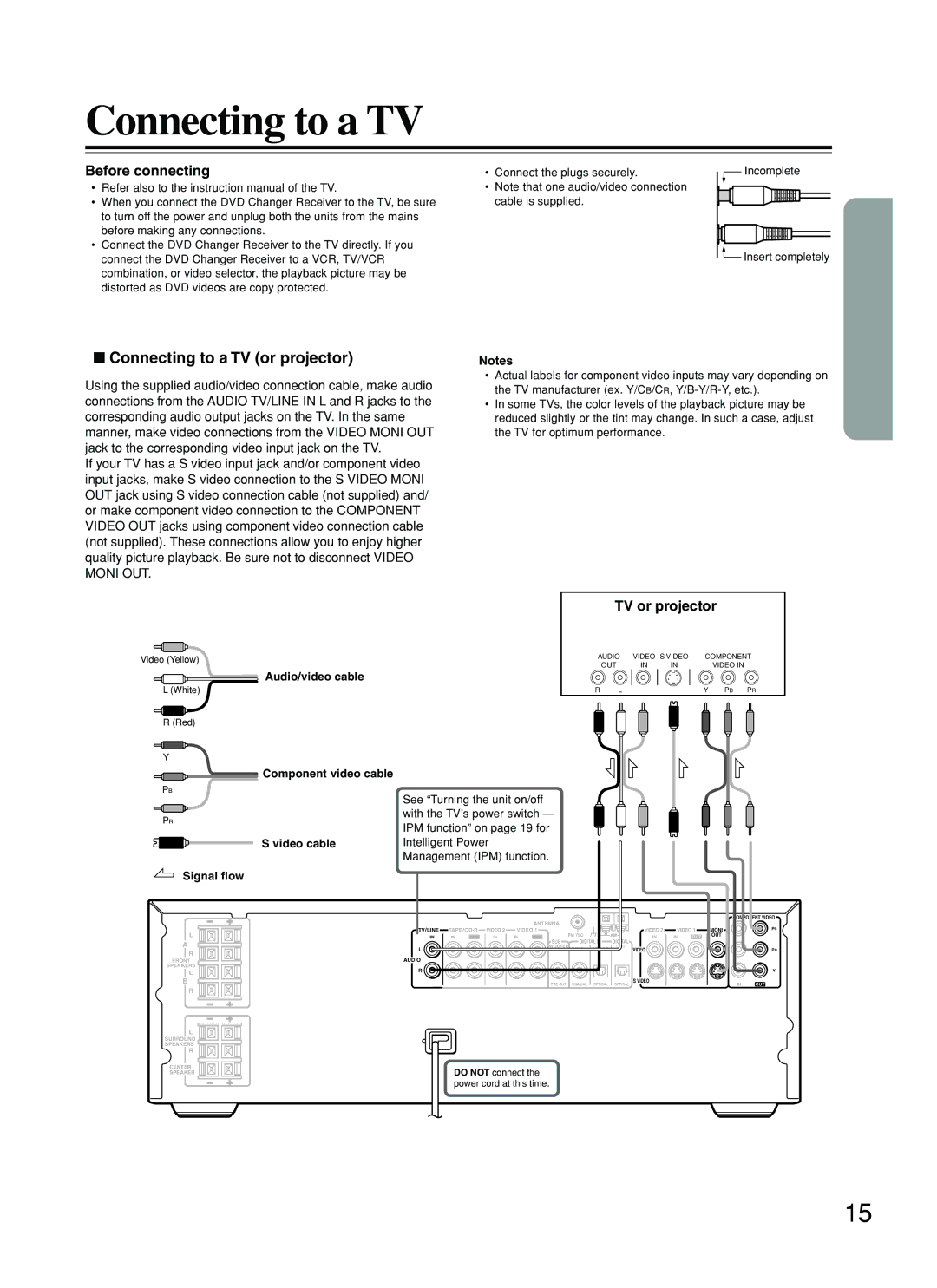
TV or projector
Connecting to a TV
Connecting to a TV or projector
Before connecting
Connecting Speakers
Two speaker system
Standard speaker placement of the Front Speakers a system
Using the provided speaker labels
Positioning Speakers
VCR, CD Recorder DVD Recorder etc
Connecting to Audio/Video Equipment
About the Video 1 and Video 2 jacks/connectors
Signal flow Component video cable
To activate the IPM function
MD Recorder, Cassette Tape
Deck, CD Recorder , Hard Disk
Recorder etc
Adjusting the position of the AM indoor antenna
Connecting the Supplied FM and AM Indoor Antennas
Connecting an AM Outdoor Antenna
Adjusting the position of the FM indoor antenna
Directional Iinkage
Connecting an FM Outdoor Antenna
Inserting the Batteries
Preparing the Remote Controller
Switching the remote controller function modes
Pointing the remote controller in the right direction
STANDBY/ON
Connecting the Power Turning on the DVD Changer Receiver
Connect the power cord to a wall outlet
Standby indicator
Speaker Setup
Selecting the Subwoofer mode
Selecting the number of speaker channels
Press DISTANCE, then press
Press Distance
Press 5/ ∞ to select the front left
Right speaker distance
Press CH SEL repeatedly to select
Speaker Setup
Adjusting Each Speakers Relative Volume Balance Test Tone
Press T. Tone
Onkyo’s original Digital Signal Processing DSP modes
Enjoying the Sound Effects
Dolby PRO Logic II Surround
TV Logic ← Studio
Enjoying the Sound Effects
Checking the Sound System of the Playing Source
Dolby PL II Movie → Dolby PL II Music Stereo
Saving the adjusted values
Volume level can be adjusted
Press T. Tone
Press Late Night
Using the Late Night Function
Press Acoustic Control on the remote controller
Boosting the Super Bass Sounds/ High Frequency Sounds
Turning on/off the Speakers A/ Speakers B Systems
Adjusting the Volume
Listening Through Headphones
Various Functions Common to all the Sources
Canceling the Sleep Timer
Various Functions Common to all the Sources
Checking the remaining time
When a Menu Screen is Displayed
Basic Playback
Playing DVDs, Video CDs, CDs and MP3s
Basic Playback
To Open or Return to the DVD or Video CD Menu Screen
To Play in Fast Reverse or Fast Forward
To Skip Chapters or Tracks
Still Frame/Slow Play
Playing Frame by Frame
To Play in Slow-motion
Repeat Play
Repeat Play
To play Discs and Tracks in random order
To cancel random play
Random Play
Random Play
Programming DVDs, CDs, Video CDs
Playing in a Favorite Order
Using the On-screen Banner Display
Viewing Disc Information
To turn off the Banner Display
Selecting a Chapter or Track
Selecting a Title
Changing the Subtitle Language
Selecting a Playback Audio Setting
To turn off the angle menu
Using the Banner Display
Changing the Camera Angle Using IntroScan Function
Using Angle on the remote controller
Using a bookmark
Using the Banner Display
MP3 Function
MP3 On-screen Display
Playing Back MP3
MP3 Memory Play
MP3 Function
Selecting MP3 Files
MP3 Repeat Play
Customizing the Settings
Making Adjustments to Setting
How to use Return
Subtitle Language
Customizing the Settings
Language Setting
Audio Language
Code No Language
Table of Languages and Their Code No
To change password
Operation Setting
Password
To input password
TV Aspect
Picture Setting
Tuning Manually
Presetting Radio Stations
Listening to the Radio
Erasing a Preset Station
Selecting Preset Stations
Enjoying the picture with the sound of another source
Playing the Connected Source
Starting Playback
Various Functions While Playing the Connected Source
Basic Recording Procedure
Recording Using the Connected Equipment
Pre-programming Codes
Learning a Pre-programming Code
Mode
Cable Satellite
Controlling TV
Press the Mode RCVR/VCR button
VPress the Mode TV button
Controlling VCR
Controlling Cable/Satellite
CBL / SATPress the Mode CBL/SAT button
Remote controller, press the Enter
Place the remote controller
Remote controller for the other
Desired Mode button on
Commands you desire from
That corresponds to the command
Remote controller of the other
Indicator on the remote controller
Erasing all the commands programmed under a Mode button
Erasing the programmed command from one button
Amplifier Symptoms Causes Remedies Pages
Troubleshooting
Troubleshooting
Symptoms Causes Remedies Pages
DVD
Symptoms Causes Remedies
Remote controller Recording
Tuner
Tuner Section
Specifications
Amplifier Section
DVD Section
Page
Onkyo U.S.A. Corporation
Onkyo Europe Electronics GmbH
Onkyo China Limited