DV-SP800
Table of Contents
Avis
Important Safeguards
For British model
Precautions
For Canadian model
For U.S. model
Regional Restriction Codes Region Number
Power
About This Manual
Recording Copyright
Getting Started
Structure of the Disc Content
Playable Discs
About Video CDs
MP3 compatibility information
Cleaning Discs
Handling Discs
Storing Discs
Supplied Accessories
Features/Supplied Accessories
Features
Using the Remote Controller
Setting the Voltage Selector Worldwide models only
Before You Start
Inserting the Batteries
Front panel
Index to Parts and Controls
Display
Rear panel
Index to Parts and Controls
Remote controller Operation buttons
Setup button
+ Setup button
Surround Mode button
Subttl button
Connecting
Connecting to a TV
Using the supplied audio/video connection cable
Before connecting
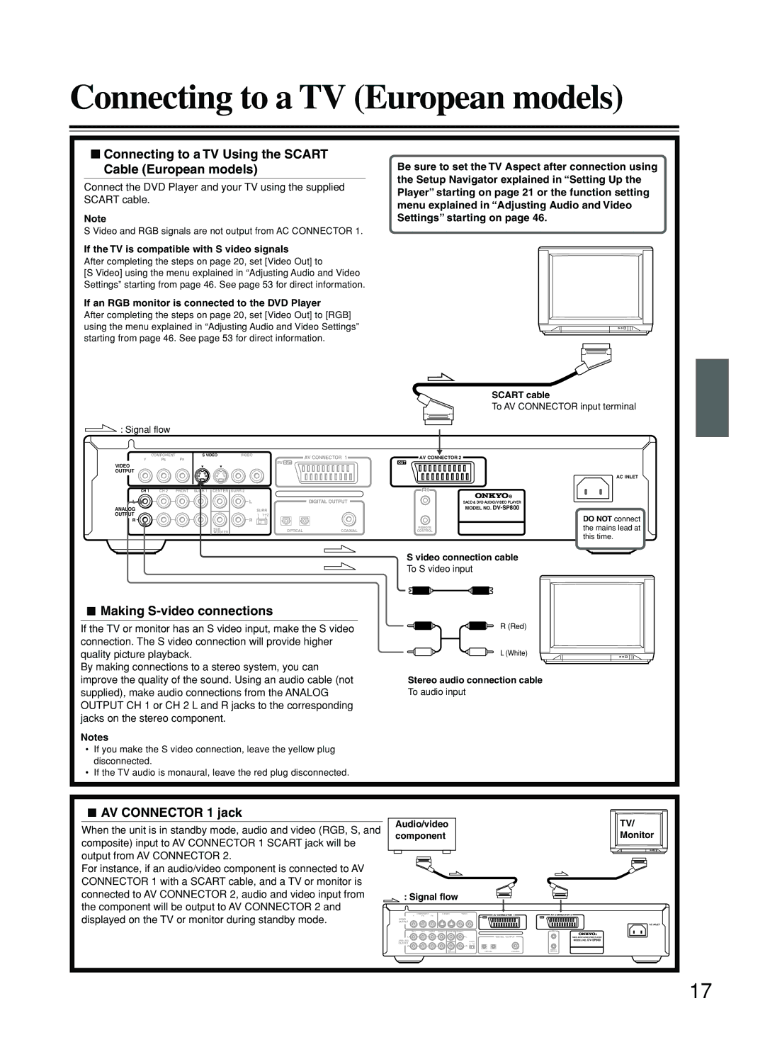
Making S-video connections
Connecting to a TV
Making component video connections
AV Connector 1 jack
Connecting to a TV European models
Connecting to a TV Using the Scart Cable European models
Optical fiber connection cable
Making a digital connection with the amplifier
Audio connection cables
Making discrete 2 channel Analog Output connections
Making discrete 5.1 channel Analog Output connections
An amplifier with
Cable To z jack
Setting the TV System Other than US and Canada models
Using the Setup Navigator
Setting Up the Player
When setting up for the first time
To exit the Setup Navigator
Setting the OSD Language On-Screen Display Language
Setting Up the Player
Setting the TV screen size
Setting the type of analog audio connections
To change other player settings in the Setup screen menus
Setting compatibility with 96 kHz output
Confirming the settings
Dolby Digital Surround
Various sound formats and sound effects
DTS Surround
MPEG2
Basic Playback
When an operation is prohibited
Playing SACDs, DVDs, Video CDs, CDs and MP3s
MP3 marks in the pages related to disc operation
When a Menu Screen is Displayed
Getting Started Using Your DVD Player
To Open or Return to the DVD or Video CD Menu Screen
To navigate a menu screen
Switching the Playback Speed
Pausing Playback
Chapter Track Skip Forward/Skip Back
Forward and Reverse Scanning
Stopping Playback and Switching Power Off
Resuming Playback from where you stopped
Press 7 once
Remove the disc
Advanced Playback
Still Frame/Slow Play
Viewing a still frame
Viewing slow playback
When performing a time search
Search using the number buttons
To perform a direct title or chapter/track
Playing bonus groups of DVD-Audio
Navigate using the following controls
Using the MP3 Navigator
Repeating a Specific Segment
Repeat Play
Repeating a Title, Group, Folder, Chapter or Track
Playing in Random Order
Random Play
To change titles, chapters, or tracks during random play
To stop random play
Programming DVDs
Playing in a Favorite Order
Press Program to enter
Programming MP3s
MP3 Program screen
Use the number buttons to enter a three-digit folder number
Additional programming options
Playing in a Favorite Order
Programming Video CDs, CDs, SACDs
To save a program in memory
To add a title/group/chapter/track to a program
To erase a program saved in memory
Press and hold Program for about 2 seconds
Viewing from a Desired Camera Angle Multi-Angle
Selecting the Camera Angle
To check whether or not a disc is recorded with angles
Press Angle during playback
Changing Audio Type
Changing the Audio Language Multi-Language Function
Selecting a Subtitle Language Multi-Language Subtitles
To clear the Last Memory location
Press Last M while in the stop mode
Press Last M during play
Load a disc that has a Last Memory point memorized
Erasing the recorded contents
Memorizing Settings for DVDs
When a disc that has memorized settings is loaded
Switching the video signal off
Turning Off the Video Signal Output
Press Video Circuit OFF on
DVD Player repeatedly
Listening through Headphones
Listening through Headphones
Adjusting the phones level
Phones level
Viewing Disc Information during while a disc is playing
Viewing Disc Information
Viewing Disc Information during while a disc is stopped
Using Dimmer function
Using the Setup Screen Menus
Adjusting Audio and Video Settings
Settings Expert Basic Factory setting
Changing to the Setup Screen Expert Menu Mode
Return Setup
VOL Enter
Adjusting the Dynamic Range of the Audio Soundtrack
Adjusting Audio and Video Settings
Setting the Audio 1 Options
Dolby Digital Out
Linear PCM Out
DTS Out
Mpeg Out
Digital Out Expert
Speaker Setting
Setting the Audio 2 Options
Sacd Playback Expert
Audio Out
Settings Fix Factory setting Variable
Gain Settings Expert
Off Factory setting
Settings
Settings 43 Letter Box Pan & Scan
Setting the TV Screen Size
Wide Factory setting
Differences in screen sizes and DVD formats
Switching the S-Video Output Expert
Setting the Video 1 Options
Component Video
Turning the Screen Saver On and Off Expert
Selecting a preprogrammed setting
Adjusting the Video Quality
Professional
Memory 1, Memory 2, and Memory
Press Display
Use the cursor button ∞ to select Video Setup and press
PureCinema DVD-Video only
Setting the Position of the On-screen Display Expert
Setting the Video 2 Options
Turning the angle indicator on and off Expert
Changing the Background of the Screen
Setting the On-screen Display OSD Language
Setting the Language Options
Selecting an audio language preference
Chinese
Selecting a subtitle language preference
Settings w/ Subtitle Language Factory setting
Selecting a DVD menu language preference
English French German Italian Spanish
Settings With Audio Selected Subtitle Factory setting
When Other is selected
Forcing subtitles to be displayed Expert
Off Assist Subtitle
Language Code List
Entering the Password
Setting the Parental Lock Level
Press Enter to set the password
Level
Changing the Password
Setting the Parental Lock Level
Setting the Country Code
Press Enter to set the new level
Other Settings
Country Code List
Auto Disc Menu Expert
Group Playback Expert
Recalling Memorized Settings
Memorizing Settings Function Memory
Resetting the Player to System Settings
To clear the Function Memory
Other remote control unit
Programming procedure
Others
SEND/LEARN
Corresponds to the command you
Other remote control unit that
Learn indicator flashes twice to
Indicate that the command has
Erasing all the commands programmed under a Mode button
Erasing the programmed command from one button
Erasing Registered codes
Register the Codes of Other Units Remote Controllers
Operate other units with the registered codes
Brand Remote Code
Preset Settings
VCR
Register the Codes of Other Units Remote Controllers
Troubleshooting
Troubleshooting
Symptoms Causes Remedies Pages
DVD Player
Troubleshooting
DVD Player Remote Controller Symptoms Causes Remedies Pages
General
Specifications
DVD Player
Outputs
Memo
Onkyo China Limited
Onkyo U.S.A. Corporation
Onkyo Europe Electronics GmbH

 : Signal flow
 Making
  AV CONNECTOR 1 jack