TX-8011 specifications
The Onkyo TX-8011 is a versatile and powerful stereo receiver that has earned a reputation for delivering high-quality audio performance at an attractive price point. Designed for those who appreciate both analog and digital audio sources, this receiver combined the best of both worlds, making it a popular choice among music enthusiasts.One of the most notable features of the TX-8011 is its robust power output. With a maximum output of 100 watts per channel, this receiver is capable of driving a wide range of speakers, ensuring clear and dynamic sound reproduction across various listening environments. The low distortion and high-current capability further enhance the audio experience, making it suitable for both casual listening and more critical applications.
The TX-8011 incorporates advanced technologies to ensure high fidelity audio playback. The receiver is equipped with a well-designed AM/FM tuner that provides excellent reception of radio signals, along with the ability to store multiple preset stations for quick access. The inclusion of a built-in phono stage allows users to directly connect their turntables, catering to vinyl enthusiasts who wish to enjoy their analog collections.
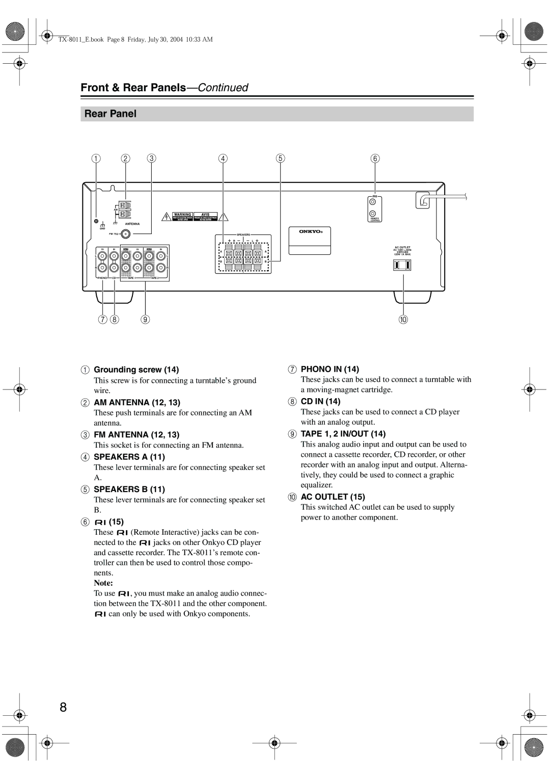
For connectivity, the TX-8011 features a variety of inputs and outputs. These include multiple line-level inputs for various audio sources, as well as a set of speaker outputs that supports A/B speaker configurations, enabling users to connect different speaker setups. The receiver also includes a headphone output for private listening.
One of the TX-8011's strengths is its user-friendly interface, which includes intuitive controls for adjusting volume, input selection, and tone adjustments like bass and treble. The receiver is designed to integrate seamlessly with existing home audio systems, making it a flexible option for users looking to upgrade or build their systems.
In terms of build quality, the TX-8011 is housed in a solid and durable chassis that not only ensures longevity but also minimizes resonance and interference. The clean aesthetic design allows it to fit into a variety of home decor styles without drawing attention away from other components.
Overall, the Onkyo TX-8011 is an excellent choice for anyone seeking a reliable and high-performing stereo receiver. With its combination of power, connectivity options, and ease of use, it stands as a compelling option in the competitive landscape of audio equipment, ensuring that users can enjoy their favorite music and media with impressive sound quality.

