Sensor Replacement
NOTE: The
IMPORTANT
•Be certain to disconnect the 24 VAC power supply either at the transformer or the fuse box. Failure to disable the power supply can result in damage to the
•The Solenoid Operator must be removed from the Valve on exposed urinal installations. Do not damage the
Figure 1A
| ORIENTATION ARROW |
Figure 1B | “TO VALVE” |
| CONNECTION |
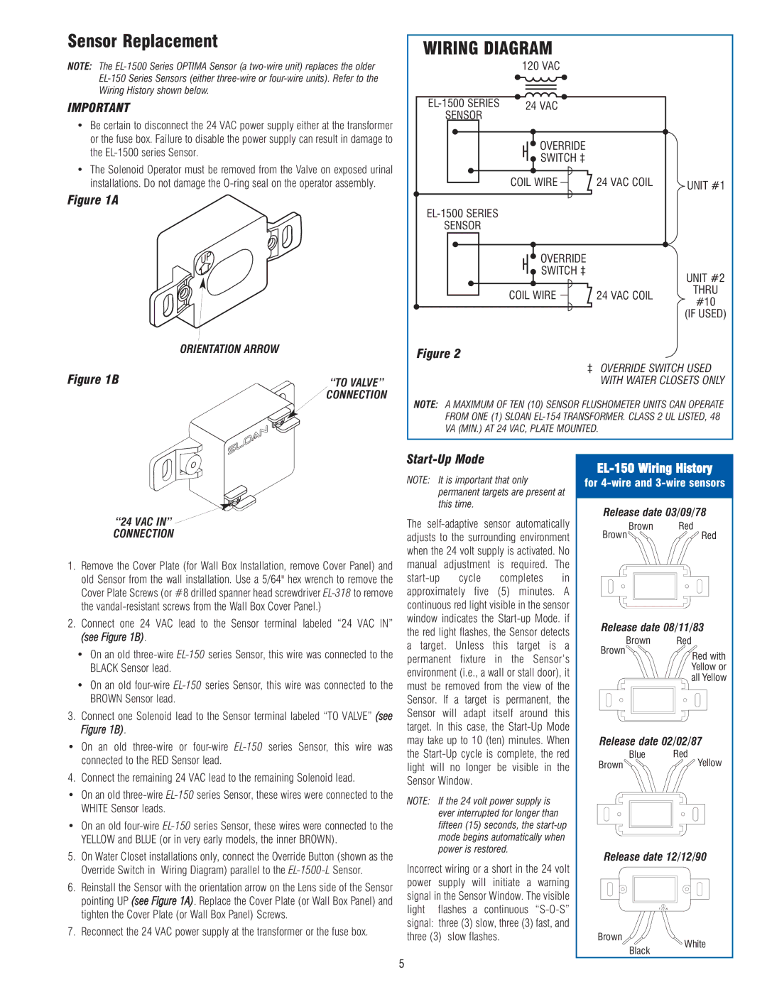
WIRING DIAGRAM
| 120 VAC |
24 VAC | |
SENSOR |
|
![]() OVERRIDE
OVERRIDE
![]() SWITCH ‡
SWITCH ‡
COIL WIRE | 24 VAC COIL | UNIT #1 |
SENSOR
![]() OVERRIDE
OVERRIDE
SWITCH ‡
UNIT #2
COIL WIRE 24 VAC COIL THRU #10
(IF USED)
Figure 2
‡ OVERRIDE SWITCH USED WITH WATER CLOSETS ONLY
NOTE: A MAXIMUM OF TEN (10) SENSOR FLUSHOMETER UNITS CAN OPERATE FROM ONE (1) SLOAN
“24 VAC IN” ![]()
CONNECTION
1.Remove the Cover Plate (for Wall Box Installation, remove Cover Panel) and old Sensor from the wall installation. Use a 5/64" hex wrench to remove the Cover Plate Screws (or #8 drilled spanner head screwdriver
2.Connect one 24 VAC lead to the Sensor terminal labeled “24 VAC IN” (see Figure 1B).
•On an old
•On an old
3.Connect one Solenoid lead to the Sensor terminal labeled “TO VALVE” (see Figure 1B).
•On an old
4. Connect the remaining 24 VAC lead to the remaining Solenoid lead.
•On an old
•On an old
5.On Water Closet installations only, connect the Override Button (shown as the Override Switch in Wiring Diagram) parallel to the
6.Reinstall the Sensor with the orientation arrow on the Lens side of the Sensor pointing UP (see Figure 1A). Replace the Cover Plate (or Wall Box Panel) and tighten the Cover Plate (or Wall Box Panel) Screws.
7.Reconnect the 24 VAC power supply at the transformer or the fuse box.
Start-Up Mode
NOTE: It is important that only permanent targets are present at this time.
The
NOTE: If the 24 volt power supply is ever interrupted for longer than fifteen (15) seconds, the
Incorrect wiring or a short in the 24 volt power supply will initiate a warning signal in the Sensor Window. The visible light flashes a continuous
EL-150 Wiring History
for
Release date 03/09/78
Brown Red
BrownRed
Release date 08/11/83
Brown | Red |
Brown | Red with |
| |
| Yellow or |
| all Yellow |
Release date 02/02/87
Blue Red
BrownYellow
Release date 12/12/90
Brown
White
Black
5