Figure 10. Placing a piece of duct, masking, or packing tape over the hex head of the azimuth axis bolt will keep it from dropping downward when you place the top baseplate onto the ground baseplate.
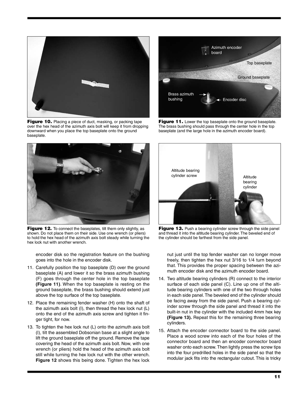
Azimuth encoder board
Top baseplate
Ground baseplate
Brass azimuth |
|
bushing | Encoder disc |
Figure 11. Lower the top baseplate onto the ground baseplate. The brass bushing should pass through the center hole in the top baseplate (and the large hole in the azimuth encoder board).
Altitude bearing |
|
cylinder screw | Altitude |
| |
| bearing |
| cylinder |
Figure 12. To connect the baseplates, tilt them only slightly, as shown. Do not place them on their side. Use one wrench (or pliers) to hold the hex head of the azimuth axis bolt steady while turning the hex lock nut with another wrench.
Figure 13. Push a bearing cylinder screw through the side panel and thread it into the altitude bearing cylinder. The beveled end of the cylinder should be farthest from the side panel.
encoder disk so the registration feature on the bushing goes into the hole in the encoder disk.
11.Carefully position the top baseplate (D) over the ground baseplate (A) and lower it so the brass azimuth bushing
(F) goes through the center hole in the top baseplate (Figure 11). When the top baseplate is resting on the ground baseplate, the brass bushing should extend just above the top surface of the top baseplate.
12.Place the remaining fender washer (H) onto the shaft of the azimuth axis bolt (I), then thread the hex lock nut (L) onto the end of the azimuth axis screw and tighten it fin- ger tight, for now.
13.To tighten the hex lock nut (L) onto the azimuth axis bolt (I), tilt the assembled Dobsonian base at a slight angle to lift the ground baseplate off the ground. Remove the tape covering the head of the azimuth axis bolt. Now, with one wrench (or pliers) hold the head of the azimuth axis bolt still while turning the hex lock nut with the other wrench. Figure 12 shows this being done. Tighten the hex lock
nut just until the top fender washer can no longer move freely, then tighten the hex nut 3/16 to 1/4 turn beyond that. This provides the proper spacing between the azi- muth encoder disk and the azimuth encoder board.
14.Two altitude bearing cylinders (R) connect to the interior surface of each side panel (C). Line up one of the alti- tude bearing cylinders with one of the two through holes in each side panel. The beveled end of the cylinder should be facing away from the side panel. Push a bearing cyl- inder screw through the side panel and thread it into the
15.Attach the encoder connector board to the side panel. Place a wood screw into each of the four holes of the connector board and then an encoder connector board washer onto each screw. Then lightly press the screw tips into the four predrilled holes in the side panel so that the modular jack fits into the rectangular cutout. This is tricky
11