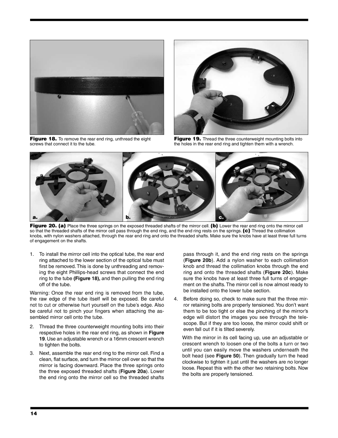
Figure 18. To remove the rear end ring, unthread the eight screws that connect it to the tube.
Figure 19. Thread the three counterweight mounting bolts into the holes in the rear end ring and tighten them with a wrench.
a. | b. | c. |
|
|
|
Figure 20. (a) Place the three springs on the exposed threaded shafts of the mirror cell. (b) Lower the rear end ring onto the mirror cell so that the threaded shafts of the mirror cell pass through the end ring, and the end ring rests on the springs. (c) Thread the collimation knobs, with nylon washers attached, through the rear end ring and onto the threaded shafts. Make sure the knobs have at least three full turns of engagement on the shafts.
1.To install the mirror cell into the optical tube, the rear end ring attached to the lower section of the optical tube must first be removed. This is done by unthreading and remov- ing the eight
Warning: Once the rear end ring is removed from the tube, the raw edge of the tube itself will be exposed. Be careful not to cut or otherwise hurt yourself on the tube’s edge. Also be careful not to pinch your fingers when attaching the as- sembled mirror cell onto the tube.
2.Thread the three counterweight mounting bolts into their respective holes in the rear end ring, as shown in Figure 19. Use an adjustable wrench or a 16mm crescent wrench to tighten the bolts.
3.Next, assemble the rear end ring to the mirror cell. Find a clean, flat surface, and turn the mirror cell over so that the mirror is facing downward. Place the three springs onto the three exposed threaded shafts (Figure 20a). Lower the end ring onto the mirror cell so the threaded shafts
pass through it, and the end ring rests on the springs (Figure 20b). Add a nylon washer to each collimation knob and thread the collimation knobs through the end ring and onto the threaded shafts (Figure 20c). Make sure the knobs have at least three full turns of engage- ment on the shafts. The mirror cell is now almost ready to be installed onto the lower tube section.
4.Before doing so, check to make sure that the three mir- ror retaining bolts are properly tensioned. You don’t want them to be too tight or else the pinching of the mirror’s edge will distort the images you see through the tele- scope. But if they are too loose, the mirror could shift or even fall out if it is tilted severely.
With the mirror in its cell facing up, use an adjustable or crescent wrench to loosen one of the bolts a turn or two until you can easily move the washers underneath the bolt head (see Figure 50). Then gradually turn the head clockwise to tighten it just until the washers are no longer loose. Repeat this with the other two retaining bolts. Now the bolts are properly tensioned.
14
