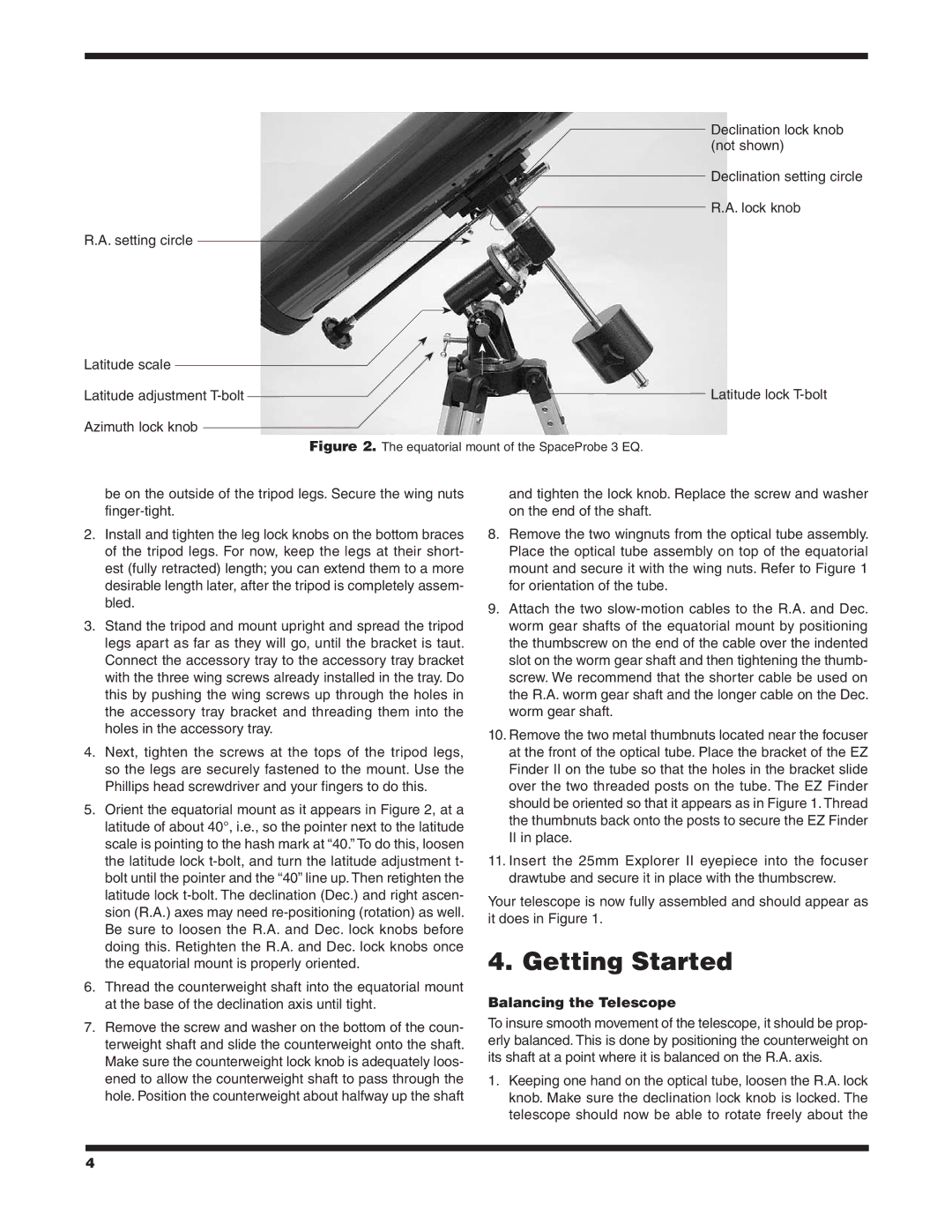
Declination lock knob (not shown)
Declination setting circle
R.A. lock knob
R.A. setting circle
Latitude scale
Latitude adjustment |
|
|
| Latitude lock |
| ||||
|
|
Azimuth lock knob
Figure 2. The equatorial mount of the SpaceProbe 3 EQ.
be on the outside of the tripod legs. Secure the wing nuts
2.Install and tighten the leg lock knobs on the bottom braces of the tripod legs. For now, keep the legs at their short- est (fully retracted) length; you can extend them to a more desirable length later, after the tripod is completely assem- bled.
3.Stand the tripod and mount upright and spread the tripod legs apart as far as they will go, until the bracket is taut. Connect the accessory tray to the accessory tray bracket with the three wing screws already installed in the tray. Do this by pushing the wing screws up through the holes in the accessory tray bracket and threading them into the holes in the accessory tray.
4.Next, tighten the screws at the tops of the tripod legs, so the legs are securely fastened to the mount. Use the Phillips head screwdriver and your fingers to do this.
5.Orient the equatorial mount as it appears in Figure 2, at a latitude of about 40°, i.e., so the pointer next to the latitude scale is pointing to the hash mark at “40.” To do this, loosen the latitude lock
6.Thread the counterweight shaft into the equatorial mount at the base of the declination axis until tight.
7.Remove the screw and washer on the bottom of the coun- terweight shaft and slide the counterweight onto the shaft. Make sure the counterweight lock knob is adequately loos- ened to allow the counterweight shaft to pass through the hole. Position the counterweight about halfway up the shaft
and tighten the lock knob. Replace the screw and washer on the end of the shaft.
8.Remove the two wingnuts from the optical tube assembly. Place the optical tube assembly on top of the equatorial mount and secure it with the wing nuts. Refer to Figure 1 for orientation of the tube.
9.Attach the two
10.Remove the two metal thumbnuts located near the focuser at the front of the optical tube. Place the bracket of the EZ Finder II on the tube so that the holes in the bracket slide over the two threaded posts on the tube. The EZ Finder should be oriented so that it appears as in Figure 1. Thread the thumbnuts back onto the posts to secure the EZ Finder II in place.
11.Insert the 25mm Explorer II eyepiece into the focuser drawtube and secure it in place with the thumbscrew.
Your telescope is now fully assembled and should appear as it does in Figure 1.
4. Getting Started
Balancing the Telescope
To insure smooth movement of the telescope, it should be prop- erly balanced. This is done by positioning the counterweight on its shaft at a point where it is balanced on the R.A. axis.
1.Keeping one hand on the optical tube, loosen the R.A. lock knob. Make sure the declination lock knob is locked. The telescope should now be able to rotate freely about the
4