Rubber | Connecting bolt |
washer | hand knob |
a.![]() Spacer
Spacer
Insertion tube
b.
Washer recessed
c.
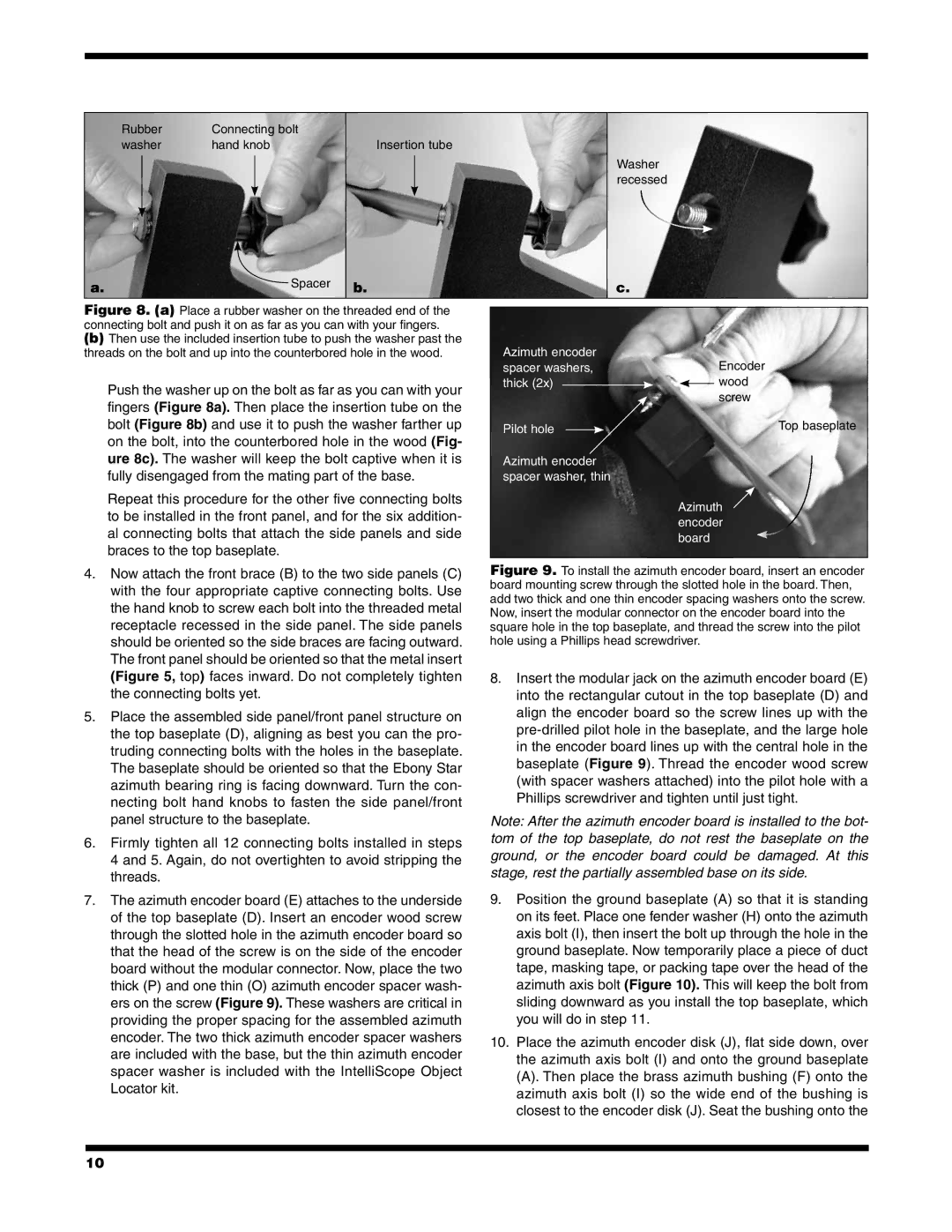
Figure 8. (a) Place a rubber washer on the threaded end of the connecting bolt and push it on as far as you can with your fingers.
(b)Then use the included insertion tube to push the washer past the threads on the bolt and up into the counterbored hole in the wood.
Push the washer up on the bolt as far as you can with your fingers (Figure 8a). Then place the insertion tube on the bolt (Figure 8b) and use it to push the washer farther up on the bolt, into the counterbored hole in the wood (Fig- ure 8c). The washer will keep the bolt captive when it is fully disengaged from the mating part of the base.
Repeat this procedure for the other five connecting bolts to be installed in the front panel, and for the six addition- al connecting bolts that attach the side panels and side braces to the top baseplate.
Azimuth encoder |
| Encoder |
spacer washers, |
| |
thick (2x) |
| wood |
| ||
|
| screw |
Pilot hole |
| Top baseplate |
Azimuth encoder spacer washer, thin
Azimuth encoder board
4.Now attach the front brace (B) to the two side panels (C) with the four appropriate captive connecting bolts. Use the hand knob to screw each bolt into the threaded metal receptacle recessed in the side panel. The side panels should be oriented so the side braces are facing outward. The front panel should be oriented so that the metal insert (Figure 5, top) faces inward. Do not completely tighten the connecting bolts yet.
5.Place the assembled side panel/front panel structure on the top baseplate (D), aligning as best you can the pro- truding connecting bolts with the holes in the baseplate. The baseplate should be oriented so that the Ebony Star azimuth bearing ring is facing downward. Turn the con- necting bolt hand knobs to fasten the side panel/front panel structure to the baseplate.
6.Firmly tighten all 12 connecting bolts installed in steps 4 and 5. Again, do not overtighten to avoid stripping the threads.
7.The azimuth encoder board (E) attaches to the underside of the top baseplate (D). Insert an encoder wood screw through the slotted hole in the azimuth encoder board so that the head of the screw is on the side of the encoder board without the modular connector. Now, place the two thick (P) and one thin (O) azimuth encoder spacer wash- ers on the screw (Figure 9). These washers are critical in providing the proper spacing for the assembled azimuth encoder. The two thick azimuth encoder spacer washers are included with the base, but the thin azimuth encoder spacer washer is included with the IntelliScope Object Locator kit.
Figure 9. To install the azimuth encoder board, insert an encoder board mounting screw through the slotted hole in the board. Then, add two thick and one thin encoder spacing washers onto the screw. Now, insert the modular connector on the encoder board into the square hole in the top baseplate, and thread the screw into the pilot hole using a Phillips head screwdriver.
8.Insert the modular jack on the azimuth encoder board (E) into the rectangular cutout in the top baseplate (D) and align the encoder board so the screw lines up with the
Note: After the azimuth encoder board is installed to the bot- tom of the top baseplate, do not rest the baseplate on the ground, or the encoder board could be damaged. At this stage, rest the partially assembled base on its side.
9.Position the ground baseplate (A) so that it is standing on its feet. Place one fender washer (H) onto the azimuth axis bolt (I), then insert the bolt up through the hole in the ground baseplate. Now temporarily place a piece of duct tape, masking tape, or packing tape over the head of the azimuth axis bolt (Figure 10). This will keep the bolt from sliding downward as you install the top baseplate, which you will do in step 11.
10.Place the azimuth encoder disk (J), flat side down, over the azimuth axis bolt (I) and onto the ground baseplate
(A). Then place the brass azimuth bushing (F) onto the azimuth axis bolt (I) so the wide end of the bushing is closest to the encoder disk (J). Seat the bushing onto the
10