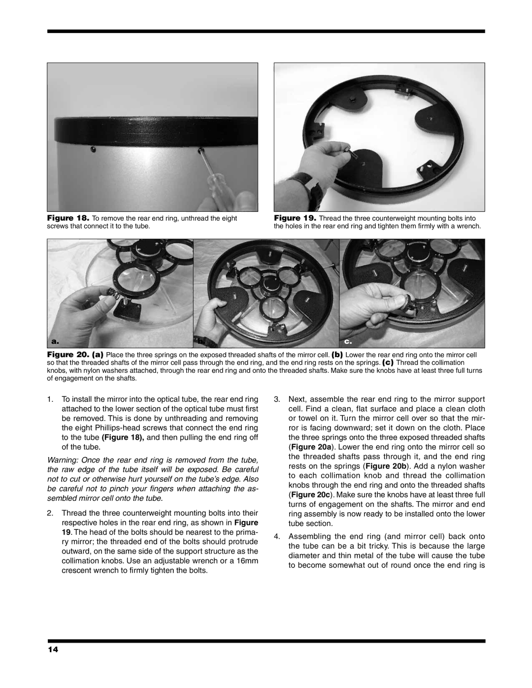
Figure 18. To remove the rear end ring, unthread the eight screws that connect it to the tube.
Figure 19. Thread the three counterweight mounting bolts into the holes in the rear end ring and tighten them firmly with a wrench.
a. | b. | c. |
|
|
|
Figure 20. (a) Place the three springs on the exposed threaded shafts of the mirror cell. (b) Lower the rear end ring onto the mirror cell so that the threaded shafts of the mirror cell pass through the end ring, and the end ring rests on the springs. (c) Thread the collimation knobs, with nylon washers attached, through the rear end ring and onto the threaded shafts. Make sure the knobs have at least three full turns of engagement on the shafts.
1.To install the mirror into the optical tube, the rear end ring attached to the lower section of the optical tube must first be removed. This is done by unthreading and removing the eight
Warning: Once the rear end ring is removed from the tube, the raw edge of the tube itself will be exposed. Be careful not to cut or otherwise hurt yourself on the tube’s edge. Also be careful not to pinch your fingers when attaching the as- sembled mirror cell onto the tube.
2.Thread the three counterweight mounting bolts into their respective holes in the rear end ring, as shown in Figure 19. The head of the bolts should be nearest to the prima- ry mirror; the threaded end of the bolts should protrude outward, on the same side of the support structure as the collimation knobs. Use an adjustable wrench or a 16mm crescent wrench to firmly tighten the bolts.
3.Next, assemble the rear end ring to the mirror support cell. Find a clean, flat surface and place a clean cloth or towel on it. Turn the mirror cell over so that the mir- ror is facing downward; set it down on the cloth. Place the three springs onto the three exposed threaded shafts (Figure 20a). Lower the end ring onto the mirror cell so the threaded shafts pass through it, and the end ring rests on the springs (Figure 20b). Add a nylon washer to each collimation knob and thread the collimation knobs through the end ring and onto the threaded shafts (Figure 20c). Make sure the knobs have at least three full turns of engagement on the shafts. The mirror and end ring assembly is now ready to be installed onto the lower tube section.
4.Assembling the end ring (and mirror cell) back onto the tube can be a bit tricky. This is because the large diameter and thin metal of the tube will cause the tube to become somewhat out of round once the end ring is
14