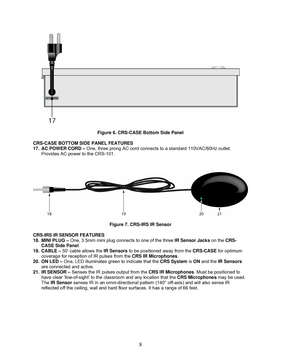
Figure 6. CRS-CASE Bottom Side Panel
CRS-CASE BOTTOM SIDE PANEL FEATURES
17.AC POWER CORD – One, three prong AC cord connects to a standard 110VAC/60Hz outlet. Provides AC power to the
Figure 7. CRS-IRS IR Sensor
CRS-IRS IR SENSOR FEATURES
18.MINI PLUG – One, 3.5mm mini plug connects to one of the three IR Sensor Jacks on the CRS- CASE Side Panel.
19.CABLE – 50’ cable allows the IR Sensors to be positioned away from the
20.ON LED – One, LED illuminates green to indicate that the CRS System is ON and the IR Sensors are connected and active.
21.IR SENSOR – Senses the IR pulses output from the CRS IR Microphones. Must be positioned to have clear
8