VPW | Arbitration | Class 2 | J1850 |
| |||
1 0 0 0 1 1 1 0 1 1 1 1 0 0 1 0 0 1 1 0 1 1 0 0 | |||
C2R-VW
Radio Replacement interface for Volkswagen
Use for Aftermarket Navigation radios that require Vehicle
Speed Sense, Reverse, Parking Brake and Illumination inputs.
Class 2 | EOD | J1850 | CRC | Class 2 | J1850 | Class 2 |
|
|
| ||||
1 1 1 0 1 0 0 0 0 1 1 0 1 1 0 1 1 1 0 0 1 1 0 0 | 1 0 0 0 1 1 1 0 1 1 1 1 0 0 1 0 0 1 1 0 1 1 0 0 | 1 1 1 0 1 0 0 0 0 1 1 0 1 1 0 1 1 1 0 0 1 1 0 0 | ||||
*
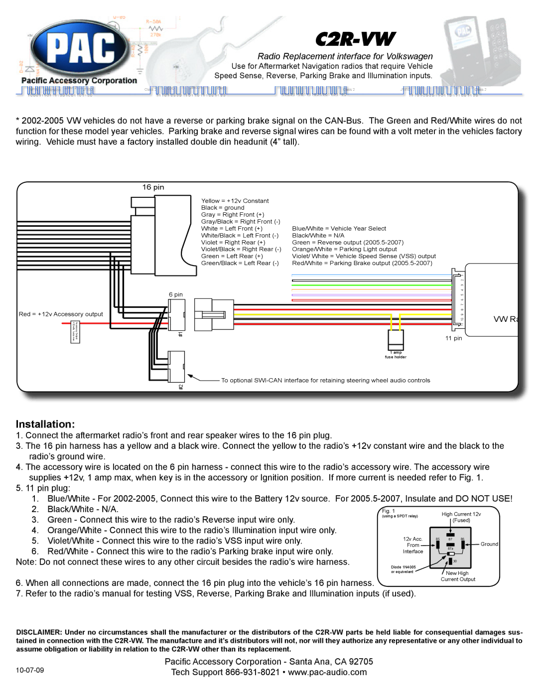
Red = +12v Accessory output
+12volts1amp max | AccessoryOutput |
. |
|
|
|
16 pin
Yellow = +12v Constant |
|
Black = ground |
|
Gray = Right Front (+) |
|
Gray/Black = Right Front |
|
White = Left Front (+) | Blue/White = Vehicle Year Select |
White/Black = Left Front | Black/White = N/A |
Violet = Right Rear (+) | Green = Reverse output |
Violet/Black = Right Rear | Orange/White = Parking Light output |
Green = Left Rear (+) | Violet/ White = Vehicle Speed Sense (VSS) output |
Green/Black = Left Rear | Red/White = Parking Brake output |
6 pin
#1
1 amp
fuse holder
![]() To optional
To optional
#2
11 10 9 8 7 6 5 4 3 2 1
11 pin
VW Ra
Installation:
1. Connect the aftermarket radio’s front and rear speaker wires to the 16 pin plug.
3.The 16 pin harness has a yellow and a black wire. Connect the yellow to the radio’s +12v constant wire and the black to the radio’s ground wire.
4.The accessory wire is located on the 6 pin harness - connect this wire to the radio’s accessory wire. The accessory wire supplies +12v, 1 amp max, when key is in the accessory or Ignition position. If more current is needed refer to Fig. 1.
5.11 pin plug:
1.Blue/White - For
2. | Black/White - N/A. | Fig. 1 |
|
| High Current 12v | ||||
3. | Green - Connect this wire to the radio’s Reverse input wire only. | (using a SPDT relay) |
|
| |||||
|
|
|
| (Fused) | |||||
4. | Orange/White - Connect this wire to the radio’s Illumination input wire only. |
|
|
|
|
|
|
|
|
5. | Violet/White - Connect this wire to the radio’s VSS input wire only. | 12v Acc. | 85 87 | 86 | Ground | ||||
From |
|
|
|
|
|
| |||
6. | Red/White - Connect this wire to the radio’s Parking brake input wire only. |
|
|
| 87a |
| |||
Interface |
|
|
|
|
| ||||
|
|
|
|
|
|
| |||
Note: Do not connect these wires to any other circuit besides the radio’s wire harness. | 30 |
|
6.When all connections are made, connect the 16 pin plug into the vehicle’s 16 pin harness.
7.Refer to the radio’s manual for testing VSS, Reverse, Parking Brake and Illumination inputs
New High
Current Output
DISCLAIMER: Under no circumstances shall the manufacturer or the distributors of the
Pacific Accessory Corporation - Santa Ana, CA 92705 | |
Tech Support |