5.Remove the screws at both sides of the wireless antenna as shown in Fig. 29 , release the wires from the adhesive tapes and put the wireless antenna aside.
Fig. 29 Removing Wireless Antenna
6.Remove the screws on LCD module holder at both sides of the LCD base cover and put it aside.
Fig. 30 Removing Wireless Antenna
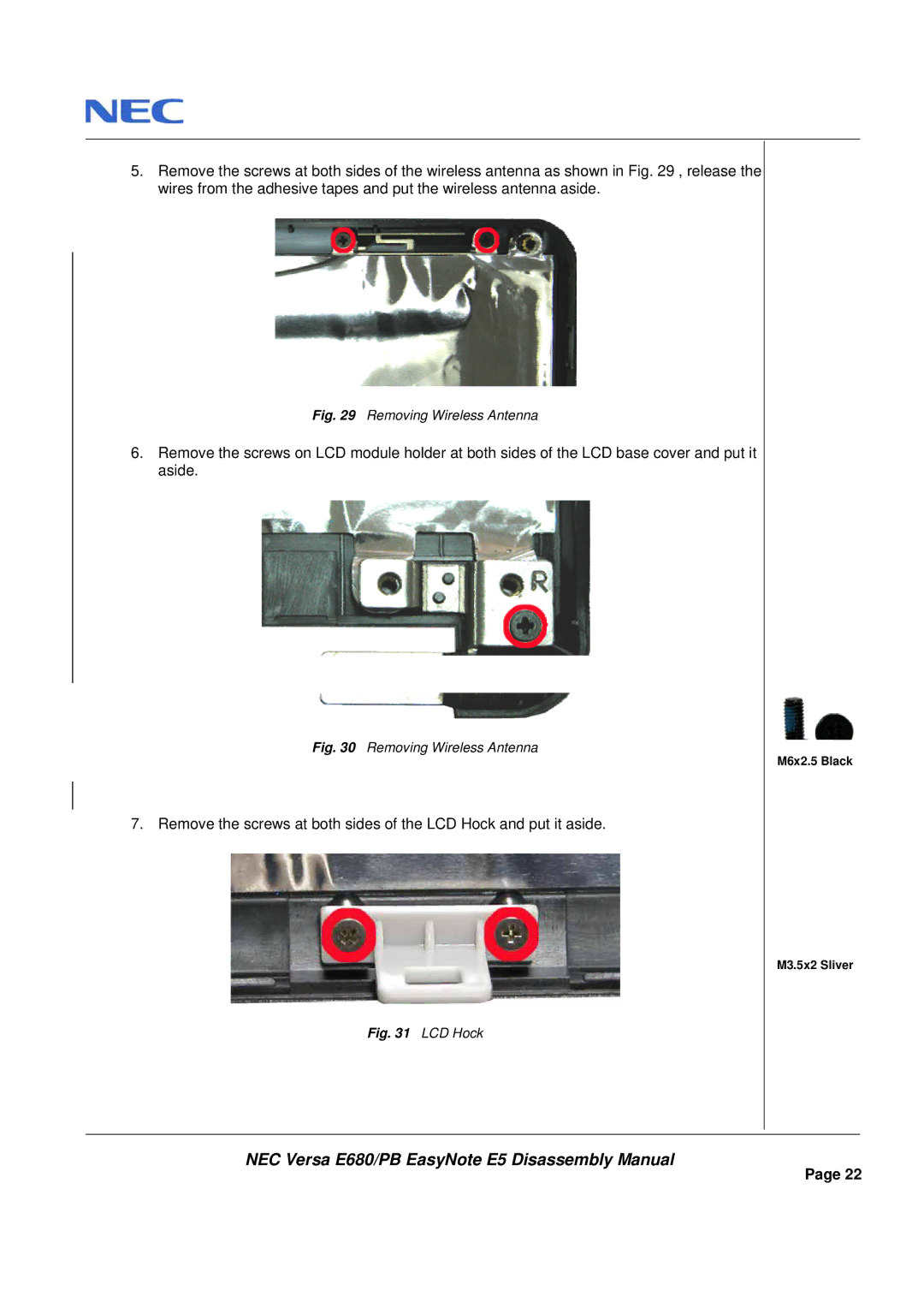
7. Remove the screws at both sides of the LCD Hock and put it aside.
Fig. 31 LCD Hock
M6x2.5 Black
M3.5x2 Sliver
NEC Versa E680/PB EasyNote E5 Disassembly Manual
Page 22