| | | | Power Switch and LED Indicator: Momentary | | | | | | | | | | | | | | | Convenience Outlet: |
| | | M7500-PRO | Pushbutton (non-latching); activates a turn-on or | | | | | | | | | | | | | | | A single outlet on the front panel of the Max 7500- |
| | | | turn-off sequence for all the outlet banks. | | | | | | | | | | | | | | | Pro provides an easy-to-reach power source for elec- |
| | | | | | | | | | | | | | | | | | | | tronic equipment typically used on a part time basis. |
| | | | Press and hold the button for 2 seconds to initiate a | | | | | | | HomeTheater Power Management | | | Such equipment includes anything from video game |
| | | | | | | | | | | | | | | | | |
| | | | turn-on or turn-off sequence. | | | | | | | | | | | | | | | | systems to camcorders. |
| | | | | | | | | | | | | | | | | | | | The convenience outlet provides clean, protected |
| | | | | | | | | | | | | | | | | | | | power for your sensitive electronic equipment. This |
| | | | Meters: The analog meters are backlit to provide | | | | | | | | | | | | | | | outlet is Always-On and will continually supply a |
| | | | the ability to view readings in a dark room. LEDs | | | | | | | | | | | | | | | steady source of power. It is important to remember |
| | | HomeTheater Power Manageme | (light emitting diodes) are used in order to provide | | | | | | | | | | | | | | | that power will be disconnected only in the event of |
| | | | durability and long life. | | | | | | | | | | | | | | | | an unsafe voltage condition. |
| | | | The Voltmeter samples the incoming voltage from | | | | | | | | | | | | | | | Sequential Startup/Shutdown: |
| | | | the wall outlet and provides a visual representation of | | | | | | | | | | | | | | | Complex audio/video systems may be susceptible |
| | | | the available power. The Voltmeter is active between | | | | | | | | | | | | | | | to voltage transients generated internally at start- |
| | | HomeTheater Power Manageme | the under-voltage and over-voltage shutoff thresholds | | | | | | | | | | | | | | | up/shutdown if all of the equipment is powered on or |
| | | | | | | | | | | | | | | | | |
| | | | (90-140V). | | | | | | | | | | | | | | | | off at the same time. This can cause speaker |
| | | | | | | | | | | | | | | | | | | | “thumps” which are not only annoying but can also |
| | | | | | | | | | | | | | | | | | | | damage the speakers. The MAX 7500-Pro is |
| | | | The Combination Meter has two display modes | | | | | | | | | | | | | | | designed to enable custom startup/shutdown |
| | | | controlled by the integrated push button on the | | | | | | | | | | | | | | | |
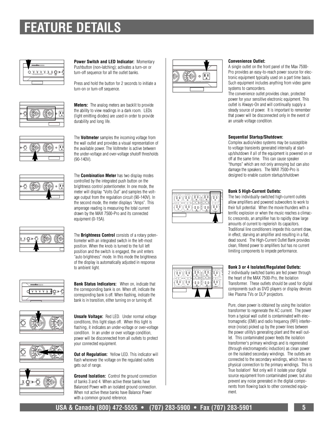
| | | | brightness control potentiometer. In one mode, the | | | | | | | | | | | | | | | Bank 5 High-Current Outlets: |
| | | HomeTheater Power Manageme | meter will display “Volts Out” and samples the volt- | KER | BANK 1 ALWAYS ON | BANK 2 SWITCHED | BANK 3 SWITCHED | | | BANK 4 SWITCHED | | BANK 5 HIGH CURRENT |
| | | | age output from the regulation circuit (90-140V). In | | | | | | MONTHLY | | INSTRUCTIOS | FOR HD VIDEO | MONTHLY | | INSTRUCTIOS | | CIRCU | The two individually-switched high-current outlets |
| | | | | | | | | | | | BANK | allow amplifiers and powered subwoofers to work to |
| | | | the second mode, the meter displays “Amps”. This | | | | | | TEST | RESET | TEST | RESET | | HC 1 |
| | | | /15A | HD SAT | | | RADIO | TEST | RESET | | ISOLATED®ULATED | TEST | RESET | | AMP | HC 2 |
| | | | amperage reading is measuring the total current | | HD CABLE | | | DVR & | TEST | | SEE | TEST | | SEE | SUB | SWITCHED | their full potential. When the movie thunders with a |
| | | | | | | REGULATED | | DIGITAL | | | | | | | | RECEIVER | |
| | | | drawn by the MAX 7500-Pro and its connected | | | | | | | | | | | | | | 3- | terrific explosion or when the music reaches a climac- |
| | | | | | 12 AMP MAX | | | | 6 AMP MAX | | | 6 AMP MAX | | 15 AMP MAX |
| | | | equipment (0-15A). | | | | | | | | | | | | | | | | tic crescendo, an amplifier has to rapidly draw large |
| | | | | | | | | | | | | | | | | | | | amounts of current to replenish its capacitors. |
| | | | | | | | | | | | | | | | | | | | Traditional line conditioners impede this current draw, |
| | | | The Brightness Control consists of a rotary poten- | | | | | | | | | | | | | | | in effect, starving an amplifier and resulting in a flat, |
| | | | tiometer with an integrated switch in the left-most | | | | | | | | | | | | | | | dead sound. The High-Current Outlet Bank provides |
| | | | position. When the knob is turned to the full left | | | | | | | | | | | | | | | clean, filtered power to amplifiers but has no current |
| | | | position and the switch is engaged, the unit enters | | | | | | | | | | | | | | | limiting components to impede performance. |
| | | | “auto brightness” mode. In this mode the brightness | | | | | | | | | | | | | | | |
| | | | of the display is automatically adjusted in response | | | | | | | | | | | | | | | Bank 3 or 4 Isolated/Regulated Outlets: |
| | | | to ambient light. | | KER | BANK 1 ALWAYS ON | BANK 2 SWITCHED | BANK 3 SWITCHED | | | BANK 4 SWITCHED | | BANK 5 HIGH CURRENT |
| | | | | | | | | | | MONTHLY | | INSTRUCTIOS | ISOLATEDFOR HD VIDEO | MONTHLY | | INSTRUCTIOS | | BANK | 2 individually switched banks are fed power through |
| | | | | | | | | | | | | | | | SWITCHED | the heart of the MAX 7500-Pro, the Isolation |
| | | | | | | | | | | | | | | | | | | CIRCU | |
| | | | | | | | | | | TEST | RESET | | | TEST | RESET | | | HC 1 | |
| | | | | | | HD CABLE | | | DVR & | | | | | | | | SUB | SWITCHED | |
| | | | | | | REGULATED | DIGITAL | | | | | | | | RECEIVER | |
| | | | Bank Status Indicators: | When on, indicate that | /15A | HD SAT | | | RADIO | TEST | RESET | | REGULATED& | TEST | RESET | | AMP | HC 2 | Transformer. These outlets should be used for digital |
| | | M7500-PRO | | | 12 AMP MAX | | | TEST | 6 AMP MAX | SEE | TEST | 6 AMP MAX | SEE | | 15 AMP MAX |
| | | | | | | | | | | | | | | | | | | I | |
| | | | | | | | | | | | | | | | | | | 3- | |
| | | | the corresponding bank is on. When off, indicate the | | | | | | | | | | | | | | | components such as DVD players or display devices |
| | | | corresponding bank is off. When flashing, indicate the | | | | | | | | | | | | | | | like Plasma TVs or DLP projectors. |
| | | | bank is in transition, either turning on or turning off. | | | | | | | | | | | | | | | Pure, clean power is obtained by using the isolation |
| | | | | | | | | | | | | | | | | | | |
| | | | | | | | | | | | | | | | | | | | transformer to regenerate the AC current. The power |
| | | | Unsafe Voltage: Red LED. Under normal voltage | | | | | | | | | | | | | | | from a typical wall outlet is contaminated with elec- |
| BRIGHTNESS | | | conditions, this light stays off. When this light is | | | | | | | | | | | | | | | tromagnetic (EMI) and radio frequency (RFI) interfer- |
O | | | | | | | | | | | | | | | | | |
| PRESS: | | | flashing, it indicates an under-voltage or over-voltage | | | | | | | | | | | | | | | ence (noise) picked up by the power lines between |
| METER SELECT | | | | | | | | | | | | | | | | | | | |
| | | | condition. In an under or over voltage condition, | | | | | | | | | | | | | | | the power utility’s generating plant and the wall out- |
| | | | power will be disconnected from all outlets to protect | | | | | | | | | | | | | | | let. This contaminated power feeds the isolation |
| | | | your connected equipment. | | | | | | | | | | | | | | | | transformer's primary windings and is regenerated |
| BRIGHTNESS | | | | | | | | | | | | | | | | | | | (through electromagnetic induction) as clean power |
O | | | | Out of Regulation: Yellow LED. This indicator will | | | | | | | | | | | | | | | on the isolated secondary windings. The outlets are |
| METER SELECT | | | | | | | | | | | | | | | | |
| PRESS: | | | | | | | | | | | | | | | | | | | |
| | | | flash whenever the voltage on the regulated outlets | | | | | | | | | | | | | | | connected to the secondary windings, which have no |
| | | | gets out of range. | | | | | | | | | | | | | | | | physical connection to the primary windings. This is |
| | | | | | | | | | | | | | | | | | | | True Isolation! Not only will it isolate your digital |
| | | | Ground Isolation: Control the ground connection | | | | | | | | | | | | | | | source equipment from contaminated power, but also |
| | | BRIGHTNESS | of banks 3 and 4. When active these banks have | | | | | | | | | | | | | | | prevent any noise generated in the digital compo- |
N | HC 2 ON | | | | | | | | | | | | | | | | |
| BANK 5 | | | | | | | | | | | | | | | | | | | |
| | | AUTO | | | | | | | | | | | | | | | | | |
H CURRENT | GROUND | PRESS: | Balanced Power with an isolated ground connection. | | | | | | | | | | | | | | | nents from flowing back to other connected equip- |
ISOLATION | METER SELECT | | | | | | | | | | | | | | |
| | ACTIVE | | | | | | | | | | | | | | | | | | |
| | | | When not active these banks have Balance Power | | | | | | | | | | | | | | | ment. |
| | | | with a common ground reference. | | | | | | | | | | | | | | | |