Parts and Their Functions
q w | e |
| CAMERA |
|
|
| SW OUT | IN | IN |
| AUDIO | VIEDO | |
|
|
| |
| OUT | OUT | |
AC IN |
|
| |
ALARM RESET IN | TAPE END OUT |
| |
|
|
| GND |
| ALARM IN COMMON REC IN | WARNING/ |
|
| REC OUT |
| |
BATTERY
![]() PUSH OPEN
PUSH OPEN
MIC
REMOTE
rty ui o!0!1
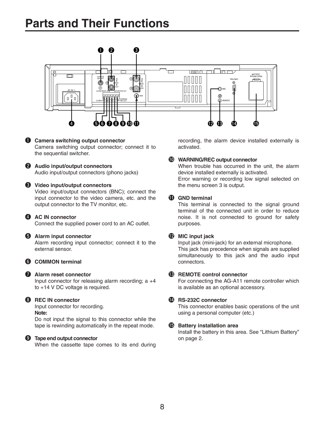
qCamera switching output connector
Camera switching output connector; connect it to the sequential switcher.
wAudio input/output connectors
Audio input/output connectors (phono jacks)
eVideo input/output connectors
Video input/output connectors (BNC); connect the input connector to the video camera, etc. and the output connector to the TV monitor, etc.
rAC IN connector
Connect the supplied power cord to an AC outlet.
tAlarm input connector
Alarm recording input connector; connect it to the external sensor.
yCOMMON terminal
uAlarm reset connector
Input connector for releasing alarm recording; a +4 to +14 V DC voltage is required.
iREC IN connector
Input connector for recording.
Note:
Do not input the signal to this connector while the tape is rewinding automatically in the repeat mode.
oTape end output connector
When the cassette tape comes to its end during
!2!3 !4 !5
recording, the alarm device installed externally is activated.
!0WARNING/REC output connector
When trouble has occurred in the unit, the alarm device installed externally is activated.
Error warning or recording low signal selected on the menu screen 3 is output.
!1GND terminal
This terminal is connected to the signal ground terminal of the connected unit in order to reduce noise. It is not connected to ground for safety purposes.
!2MIC input jack
Input jack
!3REMOTE control connector
For connecting the
!4RS-232C connector
This connector enables basic operations of the unit using a personal computer (etc.)
!5Battery installation area
Install the battery in this area. See ÒLithium BatteryÓ on page 2.
8